


A recent appliance project required a plastic electronic control box made from flame-retardant ABS. Production exposed a defect that took several rounds of adjustment to understand. The project sits at the difficult end of flame-retardant injection molding, where material behaviour and mold design can turn a small void into a production problem.
Stage 1: a straight runner and a hollow defect
The first mold used a straight runner. Its root was large, and demolding resistance appeared quickly. The result was a hollow defect in that area. The initial response was straightforward: extend holding pressure time to close the void. That helped the void but raised product density. Ejection then became the bottleneck. The ejector pins had flat edges, and there were seven of them. Brittle ABS did not deform enough to release, and all seven pins broke during ejection.
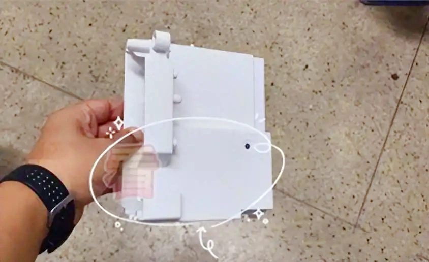
Stage 2: release agent made the surface worse
With broken pins, the team tried a release agent first. It eased demolding, but surface quality suffered and defect rates climbed. That solved one problem while creating a quality problem, so the search continued.
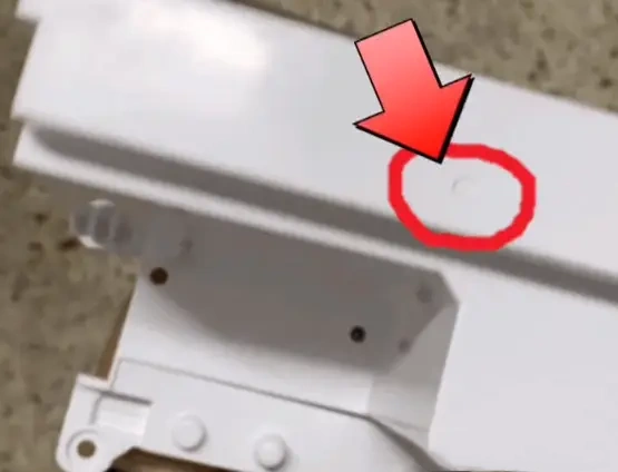
Stage 3: two-part ejection as a temporary route
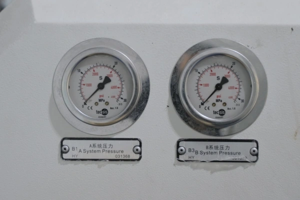
Two-part ejection was the next attempt. The first part ran very slowly and at sufficiently low pressure. Later, pressure was increased to 15 MPa and speed reduced to 3 percent. After a 5 mm distance, the press accelerated. The method worked, and the team ran a full day without breaking pins. It was inefficient, though, and only a temporary fix.
Stage 4: intermittent holding pressure
Intermittent holding pressure was meant to reduce product density. The first part used low pressure so the part could cool before the second holding phase. In theory the idea was sound. In practice, prolonged holding cooled the material head, which made it difficult to maintain pressure in the second phase. After discussion, the team shortened the straight runner and modified the mold so the runner was shorter and deeper. Some issues eased, but pins still broke. Mixing the first and second methods was still not satisfactory.
Stage 5: reverse flow, accurate but fragile
Reverse flow came next. The straight runner gate had a long sealing time. After holding pressure ended, the team increased material withdrawal to reduce pressure at the nozzle. The result was high cavity pressure and low nozzle pressure, so material flowed back and filled the void. This worked well. The method combined high holding pressure for a short time, withdrawal, and cooling time before the melt. Cavity pressure ended low, ejection was fast, and there were no voids.
The result was perfect on the parts, but the method was intricate and hard to control. If holding time should be 1.8 seconds, a 0.5 second extension could cause problems. For that reason it was not recommended for mass production. In-mold cutting was also tried through a mold modification; it failed because cutter positioning was poor for a flush cut at the gate.
Stage 6: the hot runner decision
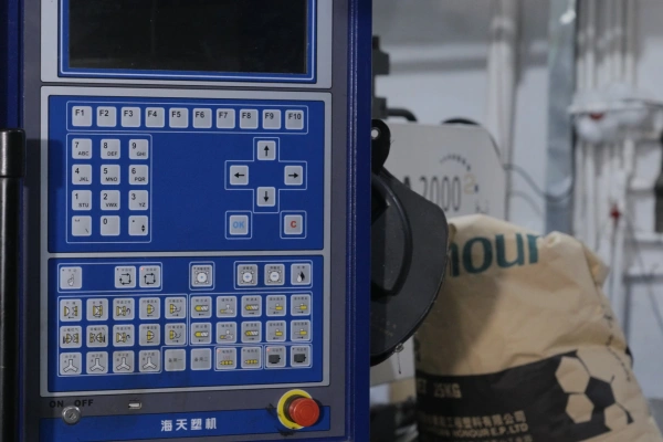
The final stage was a hot runner system, which is now in use. The timing was not an oversight. The material drove the caution. Flame-retardant ABS tends to generate black specks, and those specks are difficult to clean. Hot runners with flame-retardant ABS also produce white products, which makes impurities easier to develop and creates significant production challenges. For production stability and technical consistency, the straight runner was replaced with a hot runner.
What the case shows about flame-retardant injection molding
The case shows that improvements in injection molding often depend on the most appropriate solution rather than the theoretically optimal one. In product development with special materials, process adjustments are crucial and unavoidable. The sequence also shows why ejection, holding pressure and gate design cannot be tuned one at a time: every fix that solved the void changed the stress the pins had to survive. The constraint that finally held the project was the material itself, which is usual in flame-retardant injection molding.
Related capability: TCHD’s mold design and tooling capabilities. Drawings and production requirements can be sent for a technical review. For background on the base material, see the ABS injection molding guide, and for gate and ejection decisions earlier in the cycle, the injection molding design review.