


03Nov2026
Automated Two-Shot Molding for Precision Multi-Material Products
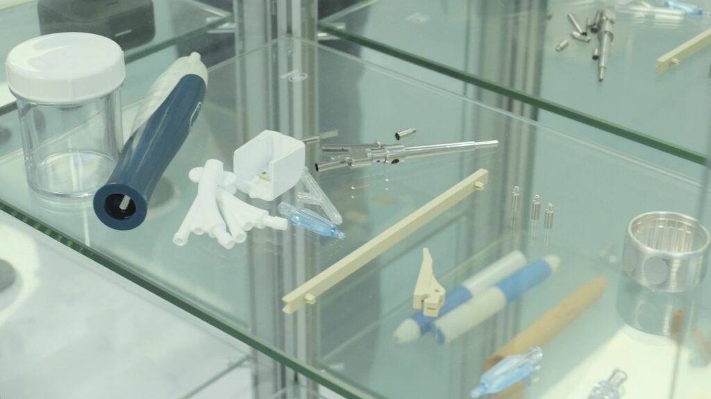
Two-shot molding produces a finished multi-material part in a single machine cycle. The first shot forms a rigid core, the tool indexes or rotates, and the second shot bonds a soft or differently colored material onto it. No assembly, no adhesive, and no second fixture. Automation is what makes the sequence repeatable at production speed. How the Cycle Works A rotating platen, a sliding core, or a stack mold moves the first-shot part into the second cavity while a fresh core is molded. Both shots run in parallel on the same cycle, which is why output per hour can exceed two separate machines working sequentially. The mold must be engineered so the two cavities share a thermal and mechanical balance. Machine and Tool Requirements A two-shot machine needs a second injection unit with independent temperature and pressure control, plus a reliable way to move the part without misalignment. Tooling needs precise indexing, hardened locating features, and a cooling layout that serves both shots. If the two resins need very different mold temperatures, the design becomes considerably more difficult. Material Pairs That Bond TPE over PP or ABS, TPU over PC, and PA over TPE with a compatibilizer are common combinations. Bonding comes from chemical affinity plus mechanical interlock: dovetails, undercuts, and through-holes. Polyolefin cores bond poorly to many elastomers, so mechanical retention should always be part of the design rather than a contingency. When Overmolding Beats Two-Shot At low volume, molding the substrate first and overmolding it later on a second machine avoids the cost of a two-shot tool. Two-shot wins when volume justifies the tooling and when assembly tolerance would be difficult to control. Cycle Time and Productivity Although two materials are molded, the second shot usually has a thinner wall and cools faster, so the added time per...
read more
03Nov2026
Telephone Injection Molding: From Precision Tooling to Reliable Assembly
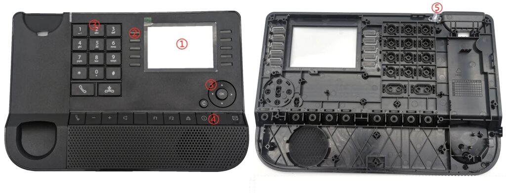
Telephone injection molding is a set of parts that must work as one product: a housing that feels solid, keys that actuate crisply, a window that stays clear, and light pipes that carry LED output evenly. Each part has its own tolerance chain, and the assembly decides whether the set succeeds. Telephone Injection Molding: The Part Set and Materials Housings usually use ABS or PC-ABS for impact strength and finish; transparent windows and light pipes need optical-grade PC or PMMA with low haze. Key buttons are often ABS or PC with a textured or polished face, and where soft touch is required, a TPE or silicone pad sits underneath. Material pairs should be chosen together, since welding and snap fits depend on compatibility. Tooling for Cosmetic Housings Visible surfaces need polished cavities, balanced gating, and draft that does not show as a highlight. Gate position should be hidden behind a battery cover or a label recess. Texture is applied to the tool, so the steel must be finished consistently across cavities, or parts from different cavities will not match under the same light. Light Pipes and Window Lenses Optical parts fail on haze, flow lines, and internal stress. Drying the resin, using a hot runner with a clean melt path, and avoiding abrupt thickness changes all reduce optical defects. Light pipes need total internal reflection, so any scratch, sink, or weld line along the path becomes a visible bright or dark spot. Controlling Stress in Transparent Parts Packing pressure and cooling uniformity decide residual stress, which shows as birefringence and can cause crazing later. Annealing after molding relieves stress in lenses that must survive drop and thermal cycling. Key Buttons and Tactile Feel Key feel comes from the geometry of the button, the dome or switch beneath it, and the...
read more
03Nov2026
3D Scanning for Reverse Engineering: From Physical Part to Manufacturable Model
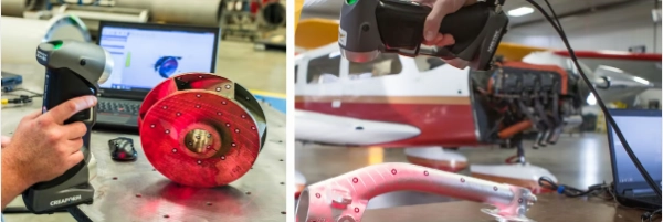
Learn how 3D scanning reverse engineering turns physical parts into digital models. Explore scanner options, point-cloud to CAD workflows, applications, and production considerations for engineers and sourcing teams.
read more
03Nov2026

Injection Molding Hidden Costs: Special Materials, Large Parts, and Trial Runs
Injection molding hidden costs rarely appear in the first quotation. They surface during parameter development, when a high-temperature resin needs a long heat soak, when a large part needs a bigger press than planned, or when a trial run consumes half a day of machine time and a barrel of material. Budgeting for those steps is the difference between a quote that holds and one that drifts. Why Specialty Resins Cost More Than Their Price High-temperature resins, glass-filled compounds, and functional grades need higher melt temperatures, tighter control, and often a dedicated barrel or screw. They process slowly, generate more scrap during startup, and may require drying equipment and longer changeover. The purchase price is only the visible part of the cost. The Real Cost of a Large Part Part size drives press tonnage, mold weight, crane capacity, and energy use. Large molds take longer to heat and stabilize, so first-off parts arrive later in the shift. Handling, packaging, and storage add cost that small-part programs never see, and a machine large enough for the tool may not be available when the schedule needs it. Injection Molding Hidden Costs in Trial Runs Parameter development is where the uncertainty lives. A specialty material may need a slow, staged heat-up and several purges before the first acceptable part. Each adjustment burns material and machine time, and a full setup can absorb half a day. Although trial runs are planned, they are rarely scheduled with the same rigor as production. Budgeting the Trial A realistic plan names the machine, the material quantity, the number of parameter loops, and the approval criteria. Trials with a written checklist finish faster than trials that restart from scratch whenever a new defect appears. Scrap and Setup Loss Startup scrap includes purging compound, short shots, and parts made...
read more
03Nov2026
IMD and IML Molding: A Practical Guide for Design and Sourcing Teams
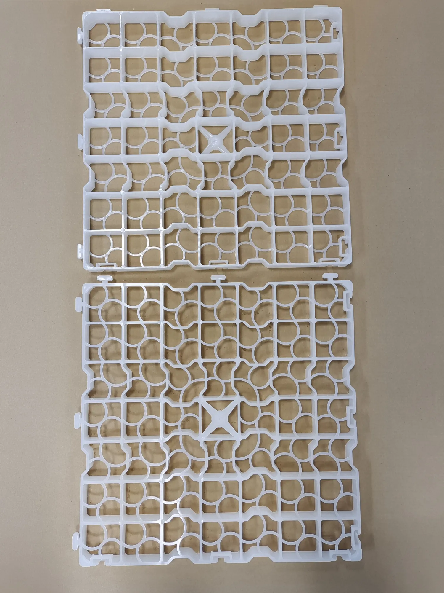
IMD and IML molding both place a printed film into the cavity so the graphic becomes part of the molded surface. The label or decorated film is bonded by the resin itself, which means the print sits behind plastic instead of on top of it. The result resists abrasion and solvents that would destroy a painted or pad-printed surface. How IML Works In-mold labeling starts with a pre-printed film, die-cut to the required outline. A robot or operator places it in the cavity against a vacuum or static charge, the mold closes, and molten resin meets the film directly. As the part cools, the plastic bonds to the label, leaving a graphic embedded in the surface with a controlled gloss or matte finish. How IMD Works In-mold decoration uses a film that carries the graphic plus a protective layer, formed to the part's curvature before molding. The film can cover the whole surface rather than a defined label area, which suits curved lenses, display windows, and large cosmetic panels. Because the film is formed first, deep draws require careful temperature control to avoid distorting the print. IMD and IML Molding: How the Two Processes Differ The choice usually follows coverage and geometry. IML suits flat or gently curved surfaces with a defined graphic area and offers low tooling cost per design change, since only the label artwork changes. IMD suits full-surface decoration, three-dimensional shapes, and hard-coated finishes, at the cost of film forming and higher scrap rates during startup. When Neither Fits Very deep draws, sharp corners, and small radii strain the film and cause wrinkles or print distortion. In those cases, a printed insert assembled afterward or a painted surface may be the more reliable route. Film and Ink Selection The film must be compatible with the resin: a...
read more
03Nov2026
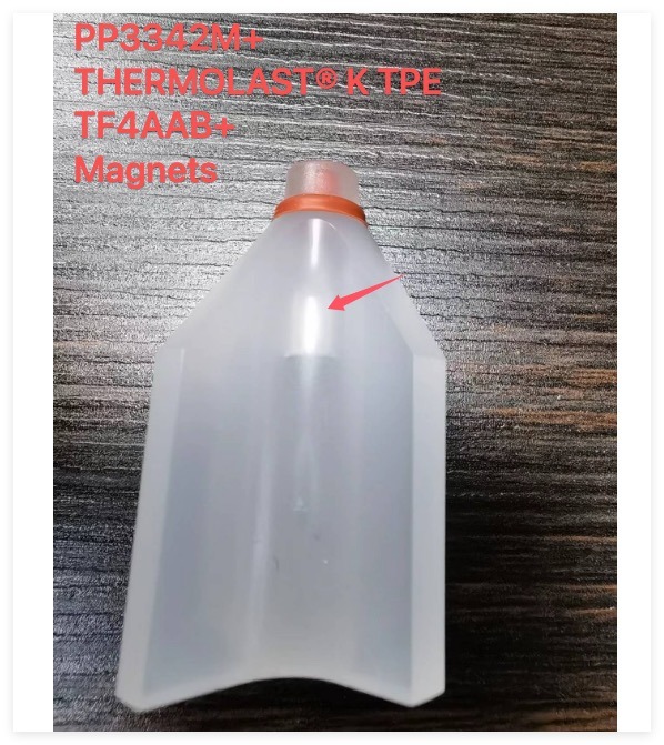
Magnet Overmolding: Design, Material, and Production Factors
Magnet overmolding encapsulates a magnet inside a molded plastic body, so the assembly arrives sealed, positioned, and protected from corrosion. The appeal is obvious for sensors, closures, and mounting hardware. The constraint is equally obvious: the magnet must survive the molding process with its magnetic strength and position intact. Why Magnet Overmolding Changes the Molding Window Neodymium magnets lose strength irreversibly above a grade-specific maximum operating temperature, and the loss accelerates near the Curie point. Molding brings molten polymer into direct contact with the magnet, so melt temperature, injection time, and cooling rate all become magnetic-performance variables rather than only processing ones. Resin Selection The resin should process below the magnet's safe temperature while still meeting structural and cosmetic needs. PP, PBT, POM, and some PA grades are common; high-temperature engineering resins are usually excluded unless the magnet grade is rated for them. Glass-filled grades add stiffness but increase wear on tooling and can crack brittle magnets during cooling. Cooling Strategy and Demagnetization Fast cooling protects the magnet but works against surface quality, because rapid solidification freezes flow marks and weld lines near the insert. A balanced approach cools the cavity side aggressively while keeping the magnet pocket insulated, and accepts a slightly longer cycle in exchange for stable magnetic output. Predicting Strength Loss A small loss is normal and should be characterized, not assumed. Measuring flux before and after molding on a sample batch establishes the real loss for the chosen resin and process, and that figure belongs in the specification. Surface Finish Trade-offs Parts molded directly over a magnet tend to show sink, flow marks, or a visible insert shadow on the cosmetic face. Magnet overmolding therefore suits internal or hidden features, brackets, and functional housings. Where appearance is critical, moving the magnet away from the visible face...
read more
03Nov2026
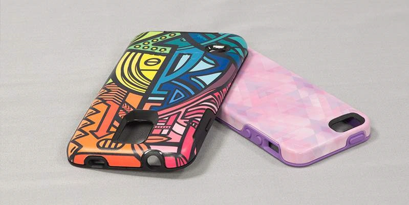
Product Surface Treatment Processes: CMF, IMD, OMD, PVD, and NCVM Guide
Surface treatment is a core part of CMF—color, material, and finish—and shapes durability, appearance, and manufacturability. This guide reviews IMD, OMD, spray coating, PVD, electroplating, NCVM, printing, laser engraving, etching, PPVD, electrophoresis, sandblasting, and rolling for engineers and sourcing teams. It also highlights process features, suitable applications, and production considerations for selecting the right finish.
read more
03Nov2026
Plastic Processing Methods: A Practical Guide for Engineers and Sourcing Teams
This guide outlines plastic processing methods—from injection molding and extrusion to thermoforming, composites, casting, and 3D printing—and highlights design, material, process, quality, and production factors that engineers and sourcing teams should evaluate.
read more
03Nov2026
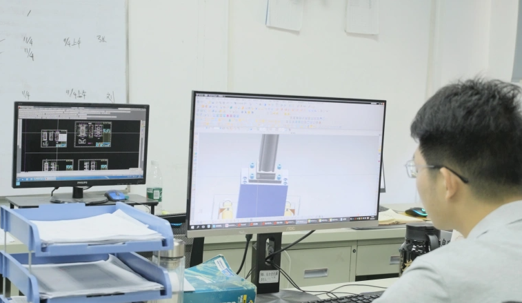
Mold Manufacturing Guide: Design, Materials, Processes, and Maintenance
Explore mold manufacturing fundamentals, including design requirements, material selection, machining methods, and maintenance practices. Learn how mold types, processes, and care influence part accuracy, production efficiency, and tool life.
read more
03Nov2026
PC Injection Molding: Process, Material, Design, and Quality Guide
PC injection molding produces parts that must be strong, clear, and dimensionally stable at the same time. Polycarbonate rewards good process control and punishes shortcuts: moisture turns into silver streaks, hot melt degrades into yellowing, and uneven cooling locks stress into the part until it crazes in service. Why Polycarbonate Is Chosen PC combines high impact strength, a wide service temperature range, good electrical insulation, and optical clarity. Those properties suit housings, lenses, light guides, and structural covers. The trade-offs are high melt viscosity, sensitivity to moisture, and a tendency to stress cracking when molded with residual stress. Grade Selection Optical grades offer low haze for lenses and windows. Flame-retardant grades serve electrical enclosures, and glass-filled grades raise stiffness at the cost of transparency. PC-ABS blends improve flow and impact for housings that do not need clarity. The grade should be selected against the service environment, since UV exposure and cleaning chemicals both attack PC. Drying and Melt Preparation PC absorbs moisture, and any residual water hydrolyses the melt, producing silver streaks and reducing molecular weight. Drying at 120 degrees Celsius for three to four hours is typical, verified with a moisture analyzer rather than by timer alone. Regrind should be limited and dried with the same discipline. PC Injection Molding: Process Settings Melt temperature usually falls between 280 and 320 degrees Celsius, with high injection speed to fill thin sections before the melt freezes. Holding pressure should be sufficient to pack without over-stressing the part, and screw speed moderate to limit shear heating. Excessive residence time degrades the melt, so shot size should be matched to the barrel capacity. Cooling and Residual Stress PC needs uniform cooling on both faces. A cavity that is colder than the core bends the part toward the hot side and leaves stress that...
read more