


Mold spotting is the practice of coating one mold surface with a thin paste, closing the tool, and reading the transfer pattern that appears. Where the paste smears, the surfaces touched; where it stays intact, a gap remains. It is one of the oldest checks in a toolroom and still one of the fastest ways to find misalignment during assembly.
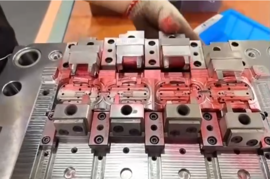
What Mold Spotting Reveals
The method exposes contact distribution rather than a single dimension. A shut-off that touches on one corner and gaps on the other will flash in production, yet both corners can measure within tolerance on a CMM. Spotting shows the interaction of two surfaces under real clamping, which is exactly the condition that decides whether a mold seals.
Paste, Applicator, and Technique
Traditional Prussian blue or red lead paste has largely given way to non-toxic alternatives with similar visibility. The layer must be thin and even: a heavy coat transfers everywhere and hides the pattern, while a starved coat shows nothing. A lint-free swab or a hard roller works better than a brush, and the surface should be clean and dry before application.
Reading the Contact Pattern
A correct shut-off shows a continuous, even band of transfer along the sealing line. Isolated bright spots mark high points that carry all the load; untouched areas show where the surfaces never met. In a spotting operation for a new tool, the mechanic blue-fits the surfaces by scraping or grinding the high points until the band becomes uniform, repeating the cycle until contact is consistent.
Spotting Within the Assembly Sequence
Spotting belongs after rough assembly and before the first trial shot, then again after any insert replacement or repair. Checking at each stage keeps errors small: a misaligned dowel found on the bench costs minutes, while the same error discovered as flash in production costs a teardown.
Shut-offs and Parting Surfaces
The parting line, cavity inserts, and core-to-cavity shut-offs are the first targets. A parting surface that touches only at the outer edge will deflect under injection pressure and flash in the middle.
Sliders, Lifters, and Ejector Pads
Moving components need their own check: the slider face against the cavity, the wedge angle, and the wear-plate contact. Spotting reveals whether a slider is being pushed back by injection pressure or whether it locks only on its heel.
Where Digital Tools Fit
3D scanning and laser alignment confirm geometry, but they measure surfaces in isolation rather than contact under clamp. The practical combination is digital verification of dimensions and spotting verification of fit. When the two disagree, the assembly condition usually explains the difference.
Common Mistakes
- Applying paste too thick, which makes every surface look like it touches
- Spotting a dirty or oily surface, which prevents transfer
- Reading a pattern without clamping at production tonnage
- Skipping re-checks after insert replacement or welding repair
- Using spotting alone as a dimensional acceptance method
Frequently Asked Questions
Is red paste still used in modern mold shops?
Yes. It is quick, cheap, and visual, and it validates contact that digital measurement cannot show directly.
How fine a mismatch can spotting reveal?
With a thin film and careful technique, contact differences in the micrometer range become visible as changes in transfer intensity.
Does spotting replace a CMM check?
No. CMM verifies geometry; spotting verifies fit. A tool needs both before tryout.
Conclusion
Mold spotting turns an invisible fit problem into a visible pattern that a toolmaker can act on. For related reading, see Prussian blue reference, our mold engineering drawings guide, and injection mold fundamentals. Contact TCHD to review your tool assembly.