


Ultrasonic welding converts high-frequency vibration into heat at the interface between two plastic parts. The joint melts and fuses in a fraction of a second, without solvent, adhesive, or fasteners. For housings that must be sealed, it is often the only assembly method that meets both the leak specification and the cycle time.
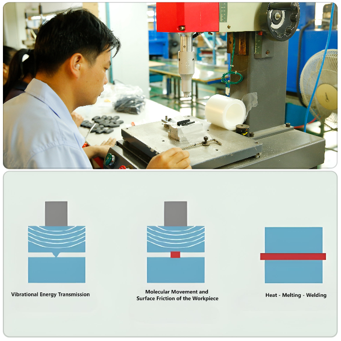
How the Process Works
A sonotrode presses the upper part against the lower one while a transducer delivers vibration at 20 to 40 kHz. The energy director, a small molded ridge on one surface, concentrates the vibration until it melts and flows into the joint. Pressure holds the parts together while the melt solidifies, usually within a second or two.
Joint Design
The energy director is a triangular ridge with a sharp apex, typically 0.5 to 1 mm tall, sized against the wall thickness. A shear joint gives a stronger hermetic seal on semi-crystalline resins because the interface slides and melts along a vertical wall. A step joint locates the parts and hides the weld line on cosmetic surfaces.
Wall Thickness and Support
The joint area must be supported by rigid walls; a thin unsupported flange flexes and welds unevenly. Where the housing is thin, a molded rib behind the joint prevents the sonotrode from marking the visible surface.
Material Compatibility
Amorphous resins such as ABS, PS, and PC weld easily because they soften gradually. Semi-crystalline resins such as PP, PE, and PA need higher amplitude and a shear joint, and they resolidify quickly. Dissimilar materials weld only when their melting ranges overlap; otherwise the joint is mechanical at best. Glass filler and mold release agents reduce weld strength.
Process Settings
- Amplitude matched to the resin and joint type
- Weld pressure high enough to keep surfaces in contact
- Weld time or energy set by collapse distance, not by a fixed timer
- Hold time and pressure long enough for the melt to set
- Tooling that supports the part below the joint
Verification and Leak Testing
Destructive peel or burst tests show joint strength; pressure decay or bubble testing shows sealing. A housing that must survive depth needs a pressure test at the rated value, not just a visual check. Production control then shifts to monitoring collapse distance, since that variable tracks weld quality in real time.
Case Pattern: Sealed Enclosures
In one underwater tracker project, the enclosure had to remain watertight at depth, and welded samples were pressure-tested at 5 bar in a lab before deployment. In a second program, a PC cover needed IP67 protection where snap fits and adhesive could not hold the seal. Both succeeded because joint geometry and process window were developed together.
Scale-Up Discipline
Welding is fast, but the variables drift: horn wear, fixture wear, and resin lot changes all shift the result. Recording amplitude, collapse distance, and energy per part on every shift gives a traceable quality record, and a fixture that locates the part by a molded feature rather than by hand keeps variation low.
Frequently Asked Questions
Can ultrasonic welding create a waterproof seal?
Yes, with a shear joint and validated process parameters. Sealing must be proven by pressure testing, not assumed.
Why does my weld look strong but leak?
Usually an incomplete melt ring, flash escaping the joint, or a joint design that cannot fill the gap.
Can painted or plated parts be welded?
Not at the joint surface. Coating must be masked or removed where the weld occurs.
Conclusion
Ultrasonic welding succeeds when joint design, resin choice, and process window are validated on real parts before scale-up. For related reading, see ultrasonic welding reference, our heat staking guide, and injection mold fundamentals. Contact TCHD to review your assembly.