


Selecting a plastic mold structure begins with the part and its production goals. Engineers and sourcing teams should evaluate the design, mold materials, molding process, quality requirements, and expected production volume together, because these factors determine which injection mold type will be practical and reliable.
Common injection mold structures include single-parting surface molds, multi-parting surface molds, oblique guide pin side-core pulling molds, oblique pin inner-core pulling molds, and hot runner molds.
Single-Parting Surface Molds (Two-Plate Molds)
A single-parting surface injection mold, also called a two-plate mold, is widely used for large gate injection molding. Its structure is simple and practical, which explains its broad use in plastic molding. The trade-off is a large gate that often needs an extra removal step and can leave gate marks on the product. It is therefore best suited to parts where surface appearance is not a primary concern.
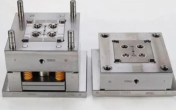
Multi-Parting Surface Molds (Three-Plate Molds)
A multi-parting surface injection mold has two or more parting surfaces, with the double-parting surface design being the most common. This design is often called a three-plate mold and is typically used for pinpoint gates, so it is also known as a small gate mold. It is widely applied in single-cavity or multi-cavity molds with pinpoint gates, molds with lateral parting mechanisms on the fixed mold side, and molds that need sequential parting because of special plastic part structures. In operation, the first parting removes the solidified runner material, while the second separates the feeding port from both the runner material and the plastic part. This eliminates the need for additional runner removal after ejection.
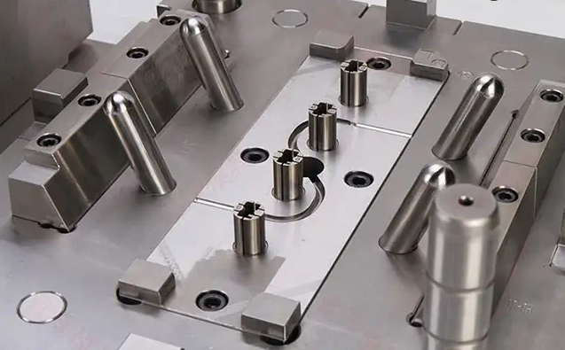
Side-Core Pulling Molds
When a plastic part has through-holes, recesses, or protrusions on its sidewall, the molding components must be able to move laterally. The full mechanism that drives the core sideways is known as a side-core pulling mechanism or lateral core-pulling mechanism. It can be powered by an oblique guide pin, hydraulics, or pneumatics; the oblique guide pin design is the most common. During mold opening, the oblique guide pin first pushes the slide block outward. After the side core has fully cleared the product, the ejection mechanism starts and ejects the molded part.
Oblique Pin Inner-Core Pulling Molds
Internal undercuts require oblique pins to form the necessary features. Molds that use oblique pins for internal core pulling are called oblique pin inner-core pulling injection molds. Their structure is relatively complex because additional oblique pin mechanisms must be built into the mold. During mold opening, the front and rear molds separate first. The injection molding machine’s ejection mechanism then pushes the mold’s ejector plate in the demolding direction. As this happens, the oblique pin gradually withdraws from the undercut area. Once it is fully released, the mold’s ejector mechanism ejects the molded product.
For simpler internal undercuts, injection mold lifters often provide a more compact alternative to full oblique pin systems.
Hot Runner Molds
Hot runner molds are being adopted more widely as automated injection molding processes advance. Their key difference from conventional molds is that the plastic in the gating system does not solidify during injection and does not come off with the molded part during demolding. For this reason, they are also called runnerless molds. Their main advantages are reduced material waste, savings in raw material, and no need for cold runner removal. They also lower pressure loss in the feeding system, allowing fuller use of injection pressure and helping to ensure molded part quality.
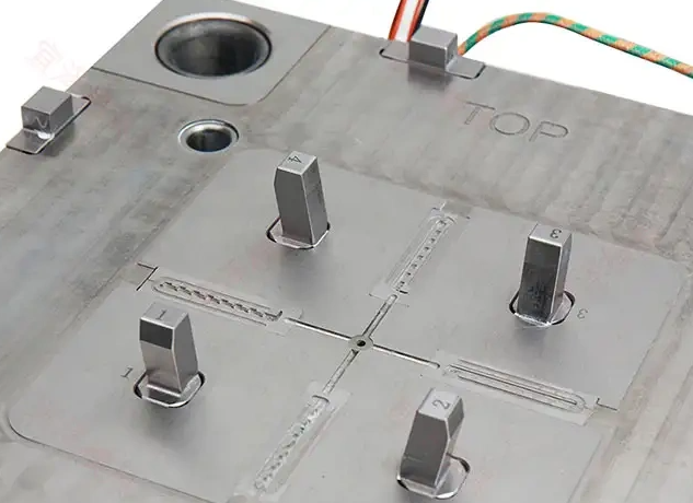
Hot runner molds are easy to recognize because they usually have cables, connectors, and junction boxes on the mold. They are complex, costly, and require strict mold temperature control, so they are best suited to mass production.
How to Choose the Right Injection Mold Type
Match the structure to the part, not to a habit. Appearance-critical parts may justify a three-plate or hot runner design; high-volume programs may absorb the higher cost of a hot runner system; simple, low-volume parts are usually best served by a two-plate mold. Compare the options with ejection strategy and gate design at the same time.
Frequently Asked Questions
Which mold type is cheapest?
A two-plate, single-parting mold is usually the lowest-cost option, but gate removal and appearance can add hidden cost.
When is a hot runner worth it?
When volume is high, material waste matters, or runner removal is impractical. The higher tooling cost is recovered through material savings and automation.
Can lifters replace side cores?
For many internal undercuts, yes. They save space and cost, but deep or multi-directional undercuts may still need a slider.
Conclusion
No single mold structure fits every part. Review the design, materials, and production volume together, then choose the simplest structure that meets quality and cost targets. For a broader overview, see injection molding. To assess these options for a specific project, explore TCHD’s mold design and tooling capabilities, or send your drawing and production requirements for a technical review.