


A trial run that produces a good part is not the same as an injection molding machine that is set up correctly. The difference shows up three hours later, or on the night shift, when the same settings produce short shots and flash. Adjustment is a sequence, and every step in it constrains the next one.
Table of Contents
- Before touching the injection molding machine
- 1. Clamp force and tonnage
- 2. Barrel and nozzle temperature
- 3. Shot size and cushion
- 4. Injection speed and profile
- 5. Packing pressure and hold time
- 6. Cooling time and mould temperature
- 7. Ejection and part removal
- 8. Recording the process window
- Frequently asked questions
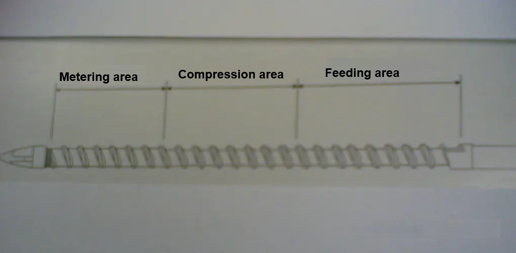
The order matters because each parameter sets a boundary. Clamp force limits how hard the injection molding machine can pack before flash appears. Melt temperature limits how fast the cavity will fill. Shot size determines whether there is a usable cushion at the end of the stroke. Adjusting them out of order produces a setting sheet that works by accident.
Before Touching the Injection Molding Machine
Three checks come before any adjustment. Confirm the mould is correctly mounted and the locating ring and nozzle are aligned. Confirm the material is the specified grade and has been dried to its data sheet. Confirm the machine’s rated shot capacity, clamp force, and tie-bar distance are adequate for the tool.
Then confirm the safety systems. Guards, interlocks, and the low-pressure mould protection setting are not part of the quality adjustment, but a machine that closes without them is not a machine anyone should be setting. Set mould protection first, at a pressure low enough to stop on an obstruction and high enough to close the tool.
A dry cycle before the first shot is worth the two minutes. It verifies ejection, core pull sequencing, and that no part is left in the cavity from the previous job.
1. Clamp Force and Tonnage
Clamp force must exceed the separating force generated by cavity pressure. The rule of thumb is 30 to 50 MPa of cavity pressure multiplied by the projected area, but the projection includes runners and any overflow, so the estimate is only a starting point.
Set the injection molding machine at the calculated tonnage, then reduce it in steps until flash just appears, and add back a margin of ten to twenty percent. Running at excessive clamp force wears the tie bars, crushes vents, and can trap air that would otherwise escape.
Tonnage also interacts with packing. If the pack pressure is raised later, the clamp requirement rises with it, so the margin chosen here constrains the packing adjustment two steps later. That is one reason the injection molding machine should be selected with headroom rather than at its limit.
2. Barrel and Nozzle Temperature
Start from the resin supplier’s recommended profile and apply it as a rising profile from feed to nozzle. A flat profile is common for engineering resins, and a reverse profile is occasionally used to reduce degradation in the feed zone.
Verify temperature with a pyrometer on a purged slug, not only with the controller display. The controller reads the barrel wall; the melt is what fills the cavity. A difference of ten degrees between the two is common on older machines and explains many unexplained quality shifts.
Nozzle temperature deserves separate attention. Too cold and a cold slug enters the cavity or blocks the gate; too hot and the material drools during mould opening. On an injection molding machine running heat-sensitive resins, the nozzle heater band is often the first component to fail and the last to be noticed.
3. Shot Size and Cushion
Shot size is set so that the screw finishes the injection stroke with a cushion of roughly five to fifteen percent of the shot volume. The cushion absorbs variation in check-valve leakage and material density, and it is the first thing to check when parts start varying between good and short.
If the cushion is too small, the process has no reserve and every fluctuation becomes a defect. If it is too large, the melt spends longer in the barrel and degrades. Adjust the shot size on the injection molding machine, not on the transfer position, when the cushion is out of range.
Check-valve wear is the hidden variable. A worn valve leaks during injection, so the cushion grows and the actual shot becomes inconsistent. A cushion that drifts upward over a production week is a maintenance signal, not a process parameter.
4. Injection Speed and Profile
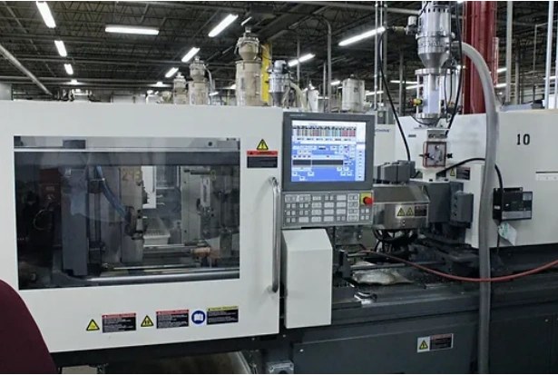
Injection speed should fill the cavity before the gate freezes, without exceeding the flow rate the material and the venting can support. Start with a single speed, evaluate the part, then profile it: slower at the gate to avoid jetting, faster through the middle, slower at the end to avoid flashing and to let air escape.
Venting is the constraint most often ignored. A fast profile on a tool with inadequate vents produces burn marks and dieseling at the last point to fill. The fix is in the tool, but the symptom is often “fixed” by slowing the injection molding machine, which hides the problem and extends the cycle.
Record the fill time at the transfer position, not just the speed setting. Fill time is the parameter that travels between machines; speed percentage does not.
5. Packing Pressure and Hold Time
Packing compensates for shrinkage while the gate is still frozen. Set the pressure from part weight: increase in steps until the weight stops rising, then back off slightly. That point is the gate seal condition, and it is specific to the material, the wall thickness, and the gate size.
Hold time should extend just beyond gate seal. A gate that is not sealed produces a part that varies with every cycle; a hold time far beyond seal adds cycle time for no benefit. Weighing the part at increasing hold times produces a clear curve and a defensible number.
Packing also drives warpage. Uneven packing across a multi-cavity tool, or across a family tool, shows up as dimensional differences between cavities that no cooling change will fix. On an injection molding machine with a single pressure setting, cavity balance is a tooling question.
6. Cooling Time and Mould Temperature
Cooling is usually the longest part of the cycle, and the easiest to set incorrectly. Set the mould temperature from the material data sheet first, then set cooling time from the thickest section and verify by measuring the part immediately after ejection and again after an hour.
A part that measures well hot and moves when cold needs more cooling or a colder mould. A part that is ejected too hot will also warp in the fixture and can deform under its own weight in the box, which appears as a customer complaint rather than a process problem.
Mould temperature control units are part of the injection molding machine setup, not an accessory. Flow rate, circuit balance, and the difference between fixed and moving halves all affect the result. A hot half and a cold half produce a warped part regardless of packing.
7. Ejection and Part Removal
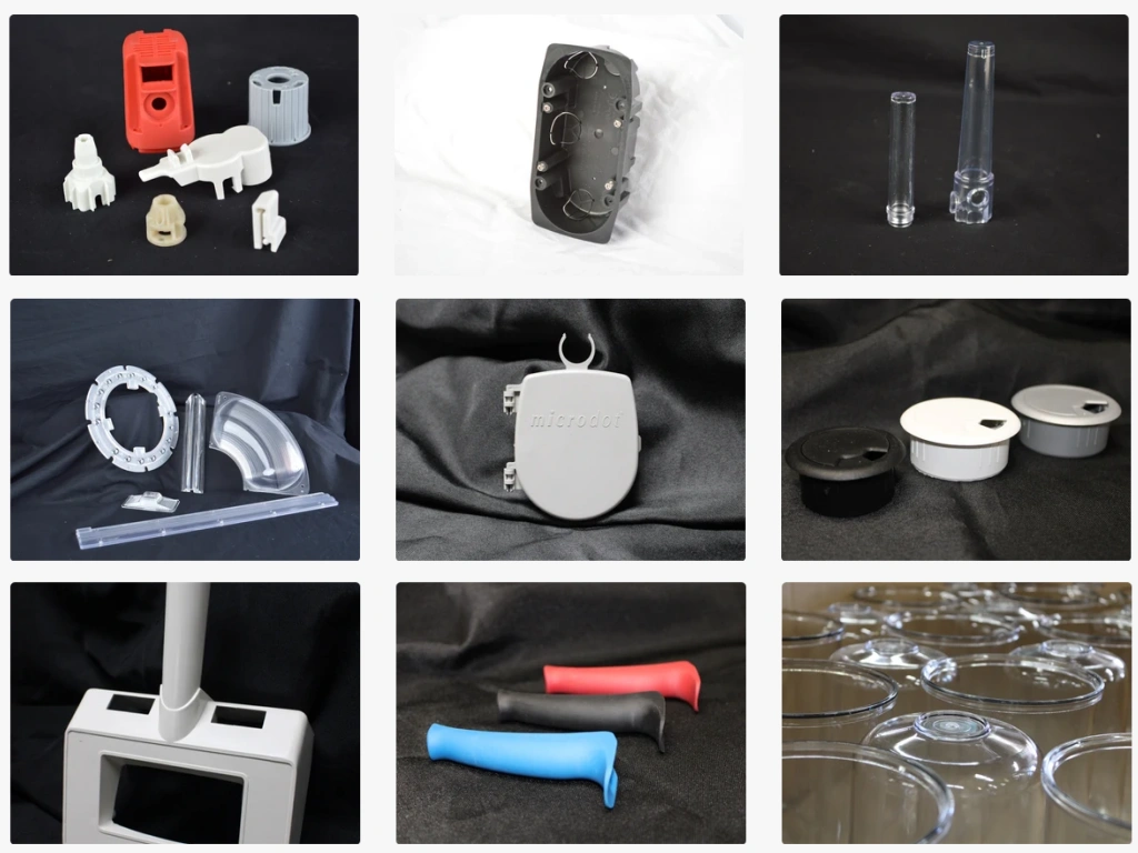
Ejection speed, stroke, and the number of ejector returns should be set so the part leaves the core without marking, dragging, or hanging. A part that sticks occasionally is a cooling or draft problem, not an ejection setting, and increasing ejection force usually makes it worse.
Robot take-out, if used, must be timed to the mould opening and must not pull the part before the ejectors have cleared it. Gripper position is part of the setup, and a gripper that distorts the part will produce a dimensional complaint that looks like a moulding problem.
After ejection, verify that no sprue or part remains in the cavity before the next close. Mould protection will catch a large obstruction, but a thin flash sliver can pass and damage the parting line over a shift.
8. Recording the Process Window
A setting sheet with a single value per parameter is not a process window. Record the nominal value and the range within which the part remains acceptable, then verify the range by running at the edges. That exercise tells the next shift what they can touch and what they cannot.
Record the machine identification, the mould number, the material lot, the drying conditions, and the date. An injection molding machine setting copied to a different machine with a different screw diameter will not reproduce the part, even with identical numbers on the screen.
Finally, document the verification. First-article dimensions, part weight, and a photograph of the accepted part are cheap to capture and settle most future arguments. Our guide to the plastic injection molding process covers the wider production context, and the cycle time guide explains how these settings translate into output.
Machine Selection Comes Before Adjustment
Some adjustment problems are selection problems. A mould that needs more clamp force than the injection molding machine can deliver will flash no matter how carefully the packing is set. A shot that requires more than eighty percent of the barrel capacity will degrade before it fills.
The three numbers to check are clamp force against projected area, shot capacity against part weight plus runner, and tie-bar distance against mould size. Add the mould height and the ejector stroke, because a tool that fits but cannot eject is still the wrong tool for that machine.
Screw diameter is the fourth. A large screw on a small shot gives long residence time and poor control; a small screw on a large shot cannot develop the pressure. When a job is transferred between plants, the injection molding machine specification matters as much as the process sheet, and a machine with a different screw will need a new window rather than a copy of the old one.
Finally, check the machine’s condition. Worn tie bars, a tired hydraulic pump, or a failing heater band will make a correct process sheet look wrong. Maintenance records belong in the trial folder, because a process that only works on a healthy injection molding machine is a process with an expiry date.
Common Adjustment Mistakes
Chasing the defect with pressure. Flash, short shots, and sink marks all invite a pressure change. None of them is primarily a pressure problem until the temperature, speed, and cushion are correct.
Changing two parameters at once. The most common reason a trial takes all day. Change one thing, run five parts, measure, decide.
Setting from the screen instead of the part. The injection molding machine reports what it was told to do. The part reports what happened.
Ignoring the material lot. A new lot with a different melt flow index behaves differently at the same settings. Record the lot and check the first parts when it changes.
Leaving the window undocumented. A process that exists only in one operator’s memory is not a process. It is a performance.
Frequently Asked Questions
How long should a setup take on an injection molding machine?
A repeat job with a documented window should be running good parts within one to two hours, including drying verification and first-article checks. A new tool takes longer because the window has to be found rather than recalled.
Should clamp force be set at the maximum?
No. Excess clamp force wears the machine, crushes vents, and traps air. Set the minimum that prevents flash with a margin, and revisit it when packing pressure changes.
Why does the cushion change during a shift?
Usually check-valve wear, material feed variation, or barrel temperature drift. Investigate in that order, and treat a steadily rising cushion as a maintenance trigger.
The Bottom Line
Injection molding machine adjustment is a sequence of constrained decisions, not a list of dials. Set the clamp, the temperatures, the shot, the speed, the packing, and the cooling in that order, verify each on the part, and write down the window. The settings that survive a night shift are the ones that were documented.
For background, the injection moulding reference covers the process fundamentals, and our defect troubleshooting guide maps symptoms to causes across material, mould, and machine.