


The injection molding process turns plastic pellets into a finished part in a cycle that lasts seconds, yet the decisions behind it reach back into tool design and forward into the shipping box. Understanding the stages, their history, and the mold choices that constrain them is what separates a stable process from one that needs re-tuning every shift.
Table of Contents
- History of the process
- The four stages
- Mold design decisions
- Process parameters and the window
- Hot runners and multi-cavity tools
- Materials and flow behaviour
- Common defects
- Quality control
- Simulation before steel
- Automation and data
- Running the first trial
- Two-shot and insert molding
- What drives part cost
- Frequently asked questions
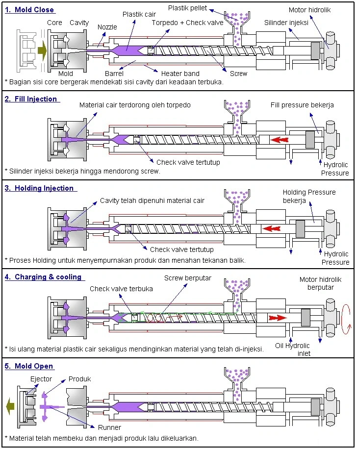
This guide walks the process from its nineteenth-century origins through the four stages that define every cycle, then through the mold design choices they depend on. The aim is a working model rather than a glossary: something a designer, a toolmaker and a setter can argue about in the same language.
History: From Celluloid to the Modern Injection Molding Process
The first machine was patented in 1872 by John Wesley Hyatt, who wanted to shape celluloid into billiard balls and dental plates. It was a plunger device, closer to a sausage stuffer than to a modern press, and it established the basic idea: heat the plastic, force it into a cavity, let it solidify.
The injection molding process changed character in 1956, when James Hendry built the first reciprocating screw machine. One screw could melt, mix and inject, which removed the separate melting stage, improved consistency, and made the cycle fast enough to compete with metal.
Most development since then has been incremental: closed-loop control, servo hydraulics, hot runner systems, and simulation that predicts fill before a tool is cut. The logic of the process has not changed, and the parameters that matter are still the ones the screw machine defined.
The Four Stages of the Injection Molding Process
Every cycle repeats the same four stages. Their durations add up to the cycle time, and the balance between them decides both part quality and part cost.
Clamping
The tool closes and builds clamp force before any material enters. Clamp force must exceed the separating force generated by cavity pressure: too little gives flash, too much crushes vents and wears the tie bars. Low-pressure mold protection is set here as well, and it is not optional.
Filling
The screw advances and fills the cavity. The speed profile controls how the melt front travels, usually slower at the gate to prevent jetting, faster through the middle, and slower at the end to let air escape. Fill time, not speed percentage, is the number worth recording.
Packing and Cooling
Packing holds pressure while the gate freezes, compensating for shrinkage. Cooling then removes heat until the part is stiff enough to eject. Cooling usually dominates the cycle, which makes mold temperature control the largest lever on cost that does not touch quality.
Ejection
The tool opens and ejector pins push the part off the core. A part that sticks is a cooling, draft or texture problem rather than an ejection setting, and adding force usually marks the part instead of releasing it.
Mold Design Decisions That Shape the Injection Molding Process
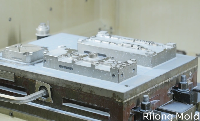
The tool fixes most of what a setter can do later. Gate location, runner size, cooling layout, draft and shrinkage allowance decide whether the injection molding process has a comfortable window or none at all.
Gate Location and Fill Balance
Gate position determines the flow path, the weld line locations, and where packing pressure actually reaches. A gate placed for convenience rather than for flow produces an overpacked region near the gate and a sink at the far end, and no amount of tuning will fix both.
Cooling Circuit Design
Cooling channels should follow the part contour at a consistent distance from the surface. Baffles and bubblers reach cores and tall features, while conformal cooling, now practical with metal printing, removes hot spots that straight drilling cannot reach.
Draft, Shrinkage and Wall Thickness
Draft of one to two degrees per side allows release without drag. Shrinkage allowance must follow the material and the wall, because semi-crystalline resins such as polypropylene shrink far more than amorphous ones such as ABS. Uniform wall thickness keeps that shrinkage predictable.
Venting and Ejection Layout
Vents at the last point to fill prevent dieseling and burn marks. Ejector placement decides whether the part leaves flat: pushing on a thin rib rather than on a boss will bow the part no matter how well the injection molding process is tuned.
Process Parameters and the Working Window
A parameter is only useful with a range attached. Melt temperature, mold temperature, injection speed, packing pressure, hold time and cooling time should each be recorded with upper and lower limits verified on the part. That range is the injection molding process window, and it is the document a night shift actually needs.
Verify the edges rather than the centre. A part molded at low melt temperature and slow fill is at the highest risk of short shots and weld lines; a part at the high end risks flash, degradation and longer cooling. If either edge fails, the window is narrower than the sheet claims.
Cushion is the cheapest health check available. A cushion that drifts upward over a shift points to check-valve wear or feed variation, and catching it early avoids a day spent chasing dimensions that were never a mold problem.
Hot Runners, Multi-Cavity Tools and Scale
A hot runner keeps the melt at temperature up to the gate, which removes the sprue and runner from the shot and shortens the cycle. It also adds a manifold with its own thermal zones, and a single cold zone produces a short shot on one cavity that looks like a process fault.
Multi-cavity tools multiply output and multiply variation. Cavity-to-cavity differences in gate size, cooling and venting show up as dimensions that never converge, and the injection molding process sheet has one set of numbers to fix them with. Balance the runner and verify each cavity before blaming the settings.
Family tools, which mold different parts in one shot, take the problem further: each cavity needs its own packing and cooling behaviour, and a single hold time will overpack one part while underpacking another. They are economical for small volumes and demanding for anyone setting the press.
Materials and How They Change the Injection Molding Process
Amorphous resins such as ABS and polycarbonate soften gradually, need higher melt temperatures, and shrink little. Semi-crystalline resins such as polypropylene and nylon have a sharp melting point, shrink one to two percent, and are far more sensitive to cooling rate.
Fillers change the injection molding process again. Glass fibre raises stiffness and reduces shrinkage, but it orients during flow, so gate position and wall thickness decide the warpage pattern. A part with thirty percent glass can warp in the opposite direction to the same part unfilled.
Drying belongs to the material specification, not to the list of optional steps. Polycarbonate, nylon and PET absorb moisture that turns to steam in the barrel, producing splay, bubbles, and a loss of impact strength that appears only after molding.
Common Defects and What They Reveal
Short shots. Usually the cavity fills too slowly, or the injection molding process has no pressure reserve left. Check cushion, fill time and venting before raising injection pressure.
Flash. A clamp or packing problem rather than a speed problem. Confirm clamp force against projected area, then confirm that packing pressure and hold time have not crept upward during the run.
Sink marks. They appear where thick sections cool last. Packing helps only while the gate is open; after that the fix is a design change such as coring the section or moving the gate.
Warpage. Differential shrinkage made visible. Uneven cooling, uneven packing and fibre orientation all produce it, and the injection molding process cannot compensate for a tool that cools one side faster than the other.
Quality Control Across the Injection Molding Process
Inspection should follow the risk. First-article parts confirm the tool and the window; in-process checks watch for drift. Weight, a small number of key dimensions and a visual check under defined lighting catch most changes before they reach a customer.
Statistical process control on a few characteristics beats inspection on many. A trend in part weight predicts a dimensional drift hours before a gauge notices it, and the process record explains the cause once the trend is visible.
Keep the process sheet, the material lot and the first-article data with the job. When a complaint arrives, the record answers in minutes what memory answers in days. Our guide to quality control in precision injection molding sets out the inspection plan that sits around this data.
Simulation Before Steel Is Cut
Fill simulation predicts the injection molding process before a tool exists: fill pattern, weld lines, air traps, packing distribution and predicted warpage. Moving a gate in software costs an afternoon; moving it in a hardened tool costs a re-cut.
Simulation is only as good as its inputs. Material data, wall thickness and gate geometry must reflect the real design, and a model that assumes uniform cooling will predict a part the actual tool cannot produce. Treat the result as a design review aid, not as a guarantee.
Automation and Data on the Shop Floor
Most modern presses log every shot: pressures, temperatures, cushion and cycle time. That data is worth little until someone defines which signals matter. Cushion, peak pressure and fill time are usually enough to detect drift early without drowning the setter in alarms.
Robot take-out, conveyor handling and automated weighing close the loop between the injection molding process and inspection. A part weighed every cycle gives a continuous record of consistency, and a step change in weight is the earliest warning that something in the process has moved.
None of it replaces the setup sheet. Automation detects that something changed; the documented window tells the next person what the process is supposed to be.
Running the First Trial
A first trial is a measurement exercise, not a production run. Start with a short shot study: fill the cavity in steps of five percent and note where the melt front stops each time. The resulting curve shows whether the tool fills in a balanced way and where the last point to fill sits, which is exactly where the vents belong.
From there, set packing from part weight and hold time from the gate seal point, then adjust cooling until the part measures the same hot and cold. Change one parameter at a time and keep five parts from each setting, because a single part records what happened once rather than what the injection molding process will do tomorrow.
Write the results on the trial sheet as they are measured. A trial reconstructed from memory the next morning is a guess with numbers attached, and the window it produces will not survive a second shift or a new setter.
Two-Shot, Overmolding and Insert Molding
Two-shot molding runs two materials in one cycle on a rotating tool, bonding a soft grip to a rigid body without an assembly step. It removes a handling operation and a bonding failure mode, and it makes the injection molding process harder to balance because both cavities must fill within the same cycle time.
Overmolding reaches a similar result on a conventional press by loading a pre-molded substrate into the tool. Bonding depends on chemical compatibility and on the substrate being clean and warm; a cold substrate produces a grip that peels in the field, months after the parts were accepted.
Insert molding places metal or a second plastic in the cavity before filling. The insert must be located so that injection pressure cannot move it, and the surrounding wall must be thick enough that shrinkage does not crack it at the corners.
What Drives the Cost of the Process
Part cost is mostly cycle time, machine rate and material. Cycle time follows wall thickness more than any other variable, because cooling scales with the square of the section: doubling a wall can quadruple the cooling requirement and turn a twenty-second cycle into a sixty-second one.
Machine rate follows clamp tonnage, so a part designed for a smaller press is cheaper to mold even at the same cycle. Runner and scrap matter as well, and a hot runner that eliminates a sprue can pay for itself on material alone during a long run.
Tool cost is a one-off, but tool life is not. A tool built for a million shots with adequate cooling and hardened gates will hold a stable injection molding process for years; a lighter tool needs maintenance that appears as variation long before it fails outright.
None of these numbers is fixed for good, but all of them are cheapest to change at the design stage. A wall thickness agreed on a drawing costs a conversation; the same change after the tool is cut costs a re-cut, a new trial and a fresh approval.
Frequently Asked Questions
How long does one cycle of the injection molding process take?
From a few seconds for a thin-walled cap to a couple of minutes for a thick technical part. Cooling usually accounts for more than half of it, and cycle time is the main driver of part cost.
What causes most defects in the injection molding process?
Temperature and cushion variation, followed by tooling limitations. Most defects are diagnosed in the order of material, mold, machine and process, and the process is rarely the first suspect that turns out to be right.
Can the process run without a hot runner?
Yes. A cold runner is simpler, cheaper and easier to maintain, and it suits short runs and colour changes. A hot runner pays back on long runs, thin walls and large multi-cavity tools.
Why does the same setting behave differently on another machine?
Screw diameter, shot capacity, hydraulic response and controller behaviour all differ. Reproduce fill time, melt temperature and cushion rather than copying percentages from the screen.
Does wall thickness affect cycle time more than material choice?
Usually yes. Cooling time scales roughly with the square of wall thickness, so a small section change moves the cycle further than a switch between two similar resins.
Can a cold runner tool be converted to a hot runner?
Sometimes. The manifold needs room in the clamp unit and new temperature control, so the conversion is a tooling project rather than a swap, and it only pays on long runs.
The Bottom Line
The injection molding process is a sequence of constrained decisions: four stages, a tool that fixes the flow path, and a window that must be measured rather than assumed. Get the mold design right, record the window, and the cycle repeats without drama.
For background, the injection moulding reference covers the process fundamentals, and our guide to design, tooling and production takes the next step into part and tool specification. The cycle time guide explains how these stages translate into output, and the defect troubleshooting guide maps symptoms to causes when something does go wrong.