


Reverse engineering a part that has no drawings or CAD files used to mean hand measurement and redrawing. That constraint has eased significantly: lower-cost 3D scanners, more approachable software, and additive manufacturing now support fast creation of digital models, prototypes, and sometimes end-use parts. For engineers and sourcing teams, the decision is not only which scanner to buy; it is also about design intent, material behavior, production method, quality control, and how the recreated model will be validated before manufacture.
In practice, reverse engineering can mean taking a product apart to understand its function, but the digital workflow is more specific: capture a physical object, rebuild it as a 3D model, and then print or manufacture it. This guide follows that path from object capture to a model that is ready for downstream use, while highlighting the main tool choices along the way. Applications extend well beyond replacing discontinued spare parts or tooling.
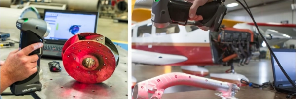
Organizations digitize legacy molds and components whose original design records have disappeared, then use modern simulation or generative design to make them lighter, stronger, or easier to produce. Automotive aftermarket teams rely on scanning for precise fit when developing accessories; even when the final item is not 3D printed, printed prototypes are common for fit and assembly checks. Studios and manufacturers that sculpt concepts in clay can scan approved shapes, move them into digital form, and continue modifying or stress-testing them. Businesses also scan competitors’ products to study construction, manufacturing choices, strengths, and weaknesses, although copyright, trademark, and intellectual-property limits always apply. In accident investigation, crashed vehicles can be scanned and compared with models of undamaged cars.
The process usually begins with scanner selection. Systems differ in size, cost, and capture method, and the right choice depends on the object’s scale and surface. Optical scanning—using structured light or laser projection—is common for reverse engineering. These devices use light, sensors, and triangulation to record reflected angles and surface points; they can capture millions of points per second at micron-level resolution, though working range may be limited to a few meters. Photogrammetry is another route: software stitches images from multiple angles into a 3D object. It is increasingly accessible through smartphones and works well for color models for online viewing, but phone-generated data is often too sparse for serious reverse engineering and may require substantial CAD work.
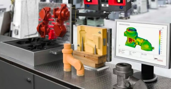
Scanning does not produce a manufacturable CAD model by itself. The scanner captures a point cloud, and mainstream CAD tools such as Fusion 360 or Solidworks cannot directly interpret raw scan data; an intermediate conversion step is required. Solidworks includes ScanTo3D, but it is limited to lower-resolution data and is not a full reverse-engineering solution. Point-cloud density affects both accuracy and effort: richer data can reduce CAD time, while low-resolution data may only outline the part and force near-complete rebuilding. Point spacing can be reduced in the scanner software, which is typically the first place to edit the data. The software then interprets points and builds a mesh—often millions of tiny triangles or other polygons—and can fill gaps where capture failed, for example on highly reflective surfaces. Scanner makers such as Artec, Evixscan, Faro, and Zeiss offer capable companion software; it does not replace CAD, but it can streamline scan-to-CAD conversion. Other systems, such as Evatronix, may depend on third-party tools like Geomagic.
Once the mesh is complete or watertight, it can be exported as an STL and sent to slicing software for 3D printing. That route is useful for exact physical replicas and fit-check prototypes. Most reverse-engineering projects, however, require more work: the model may need repair, smoothing, refinement, or surface adjustment. Production method also changes the geometry. Casting and injection molding usually require draft angles—often around three to five degrees—so parts can release from tooling, and those features will not appear in scan data. Metal additive processes may require shrinkage compensation. Choosing software is therefore a practical balance: the scanner’s own package is often enough, while specialized scan-editing tools between scanner and CAD can save significant modeling time.
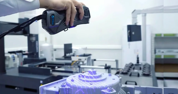
Quality depends on more than scanner resolution. Teams should confirm coverage, point-cloud density, mesh integrity, dimensional accuracy, and whether the model reflects the chosen material and manufacturing process. Matching the reverse-engineering goal to the software and production route early helps avoid rework later. For plastic injection molding projects, TCHD can review drawings and production requirements and support a technical assessment of the recreated part.