

13Oct2026
Collapsing Core Solutions for Undercut Ejection Molds: Design, Material, and Production Considerations
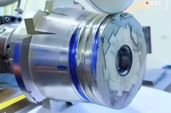
Parts with internal undercuts are difficult to eject safely. If the part is forced out before it releases, the result is scratched surfaces, sticking, stress whitening, or a rejected part. The cause is rarely ejection force alone; it is the absence of controlled clearance at the moment the part separates from the tool. How a Collapsing Core Works A collapsing core retracts before ejection, giving the part room to release without being dragged across the mold surface. The design uses a segmented structure, often six segments made of three large and three small pieces, arranged so the core expands during injection to form the undercut and contracts before the part is pushed off. The movement is driven by a center pin or wedge, timed with the ejector sequence. Segment Design and Fit Segment interfaces need a precise angle so the core collapses smoothly without binding. The angle trades travel against force: a shallow angle reduces friction but needs longer stroke. Guiding surfaces should be hardened and lubricated for the expected cycle count, and the center pin must be rigid enough to resist injection pressure without deflection. Material and Heat Treatment Core segments see sliding wear plus injection pressure, so through-hardened tool steel or a nitrided surface is common. Where the resin is abrasive, coatings extend life. The center pin should be made from a tough grade that resists bending, since a bent pin causes uneven collapse and part damage. Cooling the Core Cooling inside a segmented core is the hardest part of the design. Baffles or bubbler tubes in each segment remove heat near the undercut, where thick sections otherwise stay molten. Uneven cooling causes the part to shrink onto the core, which increases ejection force and accelerates wear. Thermal simulation before machining is cheaper than reworking a finished core....
read more
13Oct2026
Fan Blade Injection Mold Cooling Design: Zone-Specific and Conformal Cooling Strategies
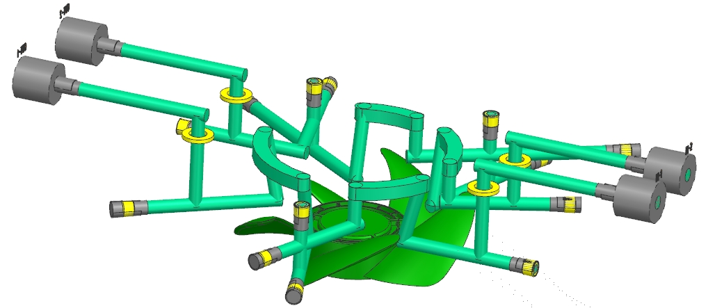
Optimize injection mold cooling design for fan blades with zone-specific cooling, conformal channels, and mold flow simulation. Learn how engineers reduce warpage, manage wall thickness variation, and improve production efficiency.
read more
13Oct2026
Injection Mold Partner Selection: How to Evaluate Precision, Quality, and Production Support
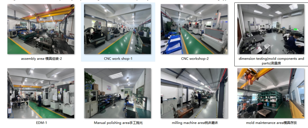
Choosing an injection mold partner is no longer a simple purchasing decision. For engineers and sourcing teams, the right supplier influences part consistency, tool life, launch speed, and total production cost. A strong evaluation covers design capability, material understanding, manufacturing processes, quality systems, and the ability to support a product from prototyping through mass production. Start With Design Capability A capable partner reads a 3D model and finds manufacturability risks before steel is cut. Ask how they run DFM, whether they provide a written report, and what happens when a design cannot be molded as drawn. Suppliers who push back with data are more valuable than those who accept everything. Equipment and Process Window Equipment capability sets the ceiling. Check machine tonnage, shot size, and control level, then confirm how the partner matches a tool to a press. Ask for the planned cavitation, cycle time, and the validation method for the process window. A partner who can explain scientific molding in concrete terms is easier to work with later. Quality System and Records ISO 9001 is a baseline. The real question is whether the system produces usable records: control plans, first-article reports with measured values, and dimensional reports that identify instruments. Ask for a sample from a similar project, including a corrective action record. Tooling Practice and Maintenance Steel grade, plate thickness, spotting capability, and tryout in-house all affect the result. Ask about maintenance policy by shot count, spare insert availability, and how they track repair history. A tool that ages well costs less per part over the program life. Production Support After Launch Launch support matters as much as build quality. Ask who owns the process sheet, how changes are documented, and how quickly a customer can reach engineering during a production issue. Response time during a launch is...
read more
13Oct2026
Electronics Enclosure Mold Design: Lessons from a TWS Charging Case
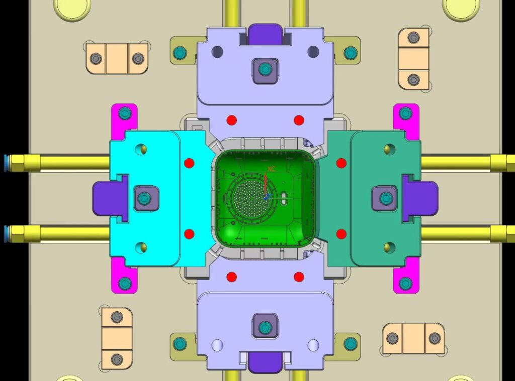
In consumer electronics, an enclosure does much more than contain internal components. It contributes structural rigidity, supports thermal management, and shapes the product's visual identity. Mold design is therefore a cross-functional challenge: it must protect brand-level aesthetics while staying repeatable in high-volume manufacturing. Why Enclosures Are Harder Than They Look A housing combines thin cosmetic walls, snap-fit features, sealing bosses, and connector openings in one part. Wall thickness must stay uniform to avoid sink on visible faces, yet the part also needs stiffness for assembly. Every feature that adds stiffness also adds tooling complexity. Lessons From a TWS Charging Case A branded TWS earbuds charging case illustrates the tension. The outer shell needed a premium finish with no gate witness, while the inner tray needed precise snap retention and USB or pogo-pin alignment. Cosmetic zones were defined early, and the parting line was moved to a hidden edge. Gate placement followed flow analysis so weld lines did not cross the visible window. Rigidity Without Thick Walls Ribs and gussets provide stiffness where solid walls cannot. Rib thickness is kept below the nominal wall to avoid sink, and rib height is limited so the section does not stay molten. Bosses are supported by gussets and cored where possible to reduce mass. Thermal and Mechanical Paths Enclosures carry heat from the charging electronics to the shell surface. Thin walls help conduction but reduce stiffness, so the design balances both. Snap features need enough flexibility to assemble repeatedly without creep, which is checked by material selection and validated by cycle testing. Process Control for Repeatability High-volume runs need a locked process window with monitoring on fill, pack, and cooling. Cavity pressure monitoring shows when a cavity drifts, and boundary samples keep cosmetic criteria consistent across cavities and shifts. Validation Before Volume First-article inspection...
read more
13Oct2026
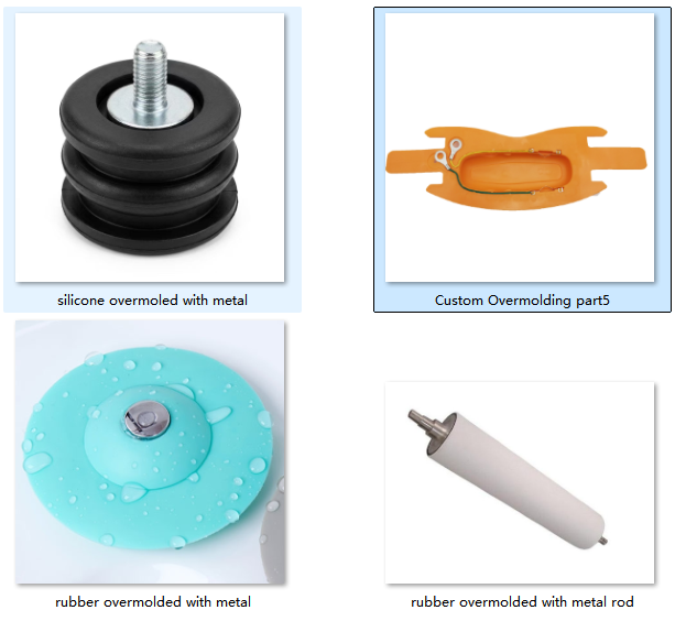
Silicone Insert Molding: Five Lessons for Durable Metal Overmolding
Silicone insert molding is a precision process, not a simple production step. Overmolding silicone onto metal inserts often follows failures: bonding that looks fine but breaks in service, dimensional movement after molding, or parts that pass a pull test but fail in the field. Five lessons from production experience cover what actually works. Lesson One: Adhesion Starts With Surface Preparation Silicone will not bond reliably to bare metal without preparation. Surface finish, cleanliness, and primer choice all matter. Aluminum and stainless behave differently, and any oil or oxide layer left on the surface reduces bond strength. Cleaning and priming should be part of the documented process, not a suggestion. Lesson Two: Choose the Right Silicone System Platinum-cured LSR bonds well to prepared metal but requires careful control of temperature and cure time. Condensation-cure systems are more forgiving but slower and may leave byproducts. The choice affects tooling, cycle time, and validation method, so it should be made with the application in mind. Lesson Three: Control the Interface Geometry Mechanical interlocks help, but they cannot carry a load alone. Undercuts and grooves increase retention while keeping the interface area large enough for chemical bonding. Sharp corners at the interface create stress concentration, so radii belong there. Lesson Four: Dimensional Movement Is a Design Issue Silicone shrinks little, but the insert and surrounding resin behave differently under temperature. Thermal cycling during validation reveals movement that a single pull test misses. Design the clearance so the part functions across the full temperature range. Lesson Five: Validate the Way the Part Fails A pull test proves bond strength, but the field failure mode is often peel, creep, or environmental exposure. Test with thermal cycling, humidity, and chemical exposure where the application demands it. Boundary conditions for the field environment belong in the test plan,...
read more
13Oct2026
Why Cheap Injection Molds Often Cost More Over Time
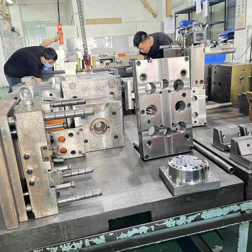
When sourcing plastic injection molds, many buyers focus first on the quoted tooling price. A lower upfront cost looks appealing, but it often hides larger expenses that appear during production: inferior materials, weak structural design, unstable processing, and insufficient quality control. Those lead to repeated repairs, inconsistent parts, and unexpected downtime. Where the Savings Actually Come From Low quotes usually come from one of four places: thinner steel plates, simplified cooling, fewer trials, or a lower steel grade. Each choice is visible in the quote if you know what to look for. The question is not whether the price is low but what was removed to make it low. Thin Plates and Structural Design Plate thickness resists deflection under clamp force. A thin plate bows, the cavity loses parallelism, and dimensions drift. The mold may still run, but tolerances widen and flash appears on one side. The repair then costs more than the original saving. Simplified Cooling Cooling is often the first thing cut. A single serpentine circuit instead of balanced circuits raises cycle time and creates temperature differences across cavities. Longer cycles run for years, so a small tooling saving becomes a permanent part cost increase. Fewer Trials and Missing Documentation Trials are where the process window is found. Fewer trials means the process is never properly validated, so the customer inherits an unstable starting point. Missing documentation compounds the problem: without a process sheet and dimensional report, troubleshooting becomes guesswork. How to Compare Quotes Fairly Steel grade and plate thickness for each component Cooling circuit count and layout Number of trials included and the validation method Documentation: process sheet, first-article report, dimensional report Warranty period or shot count Total Cost Over the Program Life Evaluate cost per part across the expected volume, including scrap, repair, downtime, and maintenance....
read more
13Oct2026

How to Reduce Injection Molding Part Costs Through Design, Material, and Process Optimization
The price of an injection molded part is rarely determined by resin alone. It is shaped by how quickly a machine can produce good parts, how much material is wasted, and how often the mold needs repair. Engineers and sourcing teams can control those variables by reviewing the project through four lenses: production efficiency, part design, material standardization, and maintenance readiness. Lever One: Production Efficiency Hot runner systems cut runner scrap and shorten cycle by reducing the cold slug that must be ejected. Balanced runners keep cavities consistent, which lowers scrap. Cycle time is dominated by cooling, so cooling layout is the highest-value change for most tools. A few seconds saved per cycle compounds across millions of parts. Lever Two: Part Design Uniform wall thickness reduces sink and warpage, which reduces scrap. Ribs and gussets add stiffness without adding mass. Draft allows release without scuffing, and gate placement avoids weld lines on cosmetic faces. Every feature that adds tooling complexity adds cost, so geometry should earn its place. Lever Three: Material Standardization Standard grades from established suppliers cost less and are easier to qualify than exotic resins. Using one resin across several parts simplifies drying, color, and inventory. Where a specialty resin is required, confirm the benefit is functional rather than habitual. Lever Four: Maintenance Readiness A well-maintained mold runs a stable process and avoids unplanned downtime. Schedule cleaning and inspection by shot count, check vent depth and gate erosion, and keep a repair history. Spare inserts for high-wear cavities reduce downtime when a repair is needed. Where Cost Is Actually Lost Scrap from unstable fill or packing Extended cycle from poor cooling Runner and sprue waste from cold runners Repair downtime from skipped maintenance Requalification after undocumented process changes Measuring the Effect Track cost per part, not cost per...
read more
13Oct2026
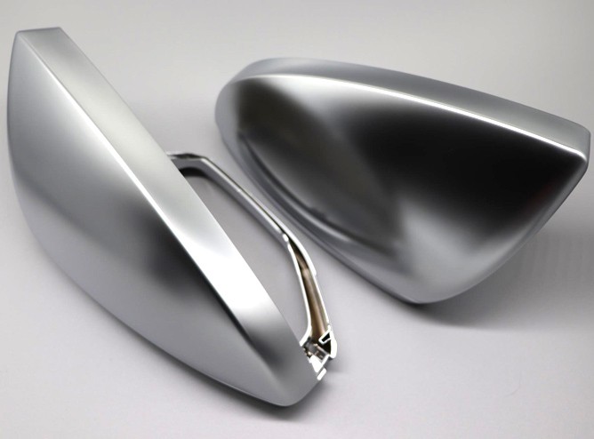
Elevating Plastic Components: A Strategic Guide to Surface Finishing Techniques
Injection molding provides the structural foundation, but strategic surface treatment defines the final user experience. For engineering and procurement teams, choosing a post-processing method is a design decision that bridges functionality and market appeal, and it affects tooling, material choice, assembly, validation, and cost. Painting and Coating Painting offers the widest color range and the best cost per unit for high volume. It requires good surface preparation and a primer to avoid adhesion problems, and it adds environmental and labor steps. Soft-touch coatings create a premium feel but wear at edges, so film thickness and application method matter. Plating Electroplating adds corrosion resistance and a metallic look on ABS and PC/ABS. The process combines etching, activation, and copper, nickel, and chromium layers. Adhesion depends on substrate and surface prep, and thickness changes dimensions, so critical features need allowance. IMD and OMD In-mold decoration and in-mold forming place a decorated film inside the tool, so the graphic becomes part of the part with no secondary step. IMD suits flat or gently curved surfaces; OMD handles deeper 3D shapes. Both protect graphics from wear, which painting cannot match, but they require tooling changes and careful film handling. PVD and NCVM Physical vapor deposition produces hard, decorative, and functional coatings with excellent wear resistance, at higher cost and usually in a vacuum process. Non-conductive vacuum metalization gives a metallic appearance without electrical conductivity, which matters for housings that must stay insulated. Texture and Mold Finish The cheapest finish is the one built into the tool. Textures hide minor flow marks, reduce visible scratches, and change the tactile feel. Texture depth must be agreed before machining, since it changes release force and cleaning requirements. Choosing by Function Color and cost: painting Graphic protection: IMD or OMD Metallic look with wear: PVD Metallic look without...
read more
13Oct2026

Two-Shot Molding vs Overmolding: Choosing the Right Multi-Material Process
Multi-material parts are increasingly common in consumer, medical, and automotive products. Once the decision to combine materials is made, the next question is which process: two-shot molding or overmolding. Both produce a part with two materials, but they differ in tooling, equipment, cycle, and the quality of the bond. The Core Difference Two-shot molding injects both materials in one machine cycle using a rotating platen or indexing tool. Overmolding molds a substrate first, then loads it into a second tool to receive the overmold layer. The first keeps everything inside one cycle; the second splits production into two operations. Tooling and Equipment Two-shot needs a tool with two cavity sets and a reliable index, plus a machine with two injection units. The investment is higher, and the tool is harder to modify. Overmolding needs two simpler tools and a loading system, which can be manual, robotic, or reel-fed. For prototypes, overmolding can often reuse an existing substrate part. Bond Quality Two-shot bonds the second material to a substrate that is still warm, which usually produces better adhesion and a cleaner interface. Overmolding depends on substrate surface condition and material compatibility, and handling between steps introduces contamination risk. Where peel strength is critical, two-shot has the advantage. Cycle Time and Throughput A two-shot cycle is longer than a single shot, but it replaces two operations, so total throughput often improves and work-in-progress disappears. Overmolding adds handling time and a second setup, but each step can run at its own optimum. Design Freedom Two-shot allows thinner overmold layers and sharper material boundaries. Overmolding tolerates more design change because each tool can be revised independently. Where the design is still evolving, overmolding is more forgiving. Cost and Break-Even Below roughly tens of thousands of parts, overmolding usually wins on tooling cost. Above that,...
read more
13Oct2026
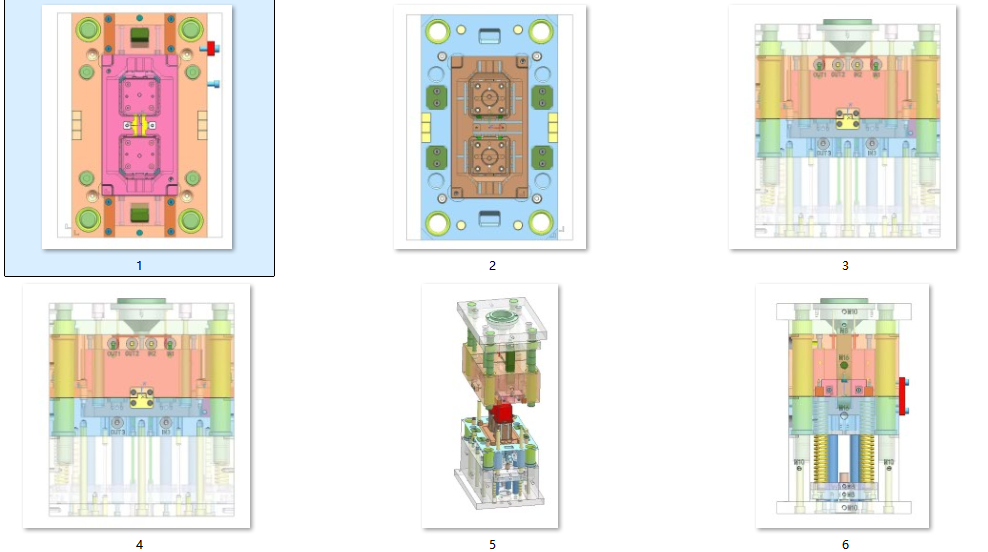
Mold Engineering Drawings: Ensuring Smooth Mold Transfer and Startup
When a new mold arrives at a plant, the real test begins. The tool is mounted, connected, and prepared for startup. If problems appear immediately, the cause is not always poor workmanship. In many cases the underlying issue is a lack of alignment between mold structure, machine interfaces, mounting dimensions, and assembly expectations. Why Drawings Decide Startup Success Mold engineering drawings are the contract between the toolmaker and the production plant. They state where the locating ring sits, how the ejector pattern is arranged, what the nozzle radius is, and which circuits feed which zone. When those details are assumed rather than documented, the first trial becomes a negotiation instead of a validation. Interface Dimensions to Confirm Locating ring diameter and nozzle radius Platen bolt pattern, slot spacing, and clamp clearance Mold height, width, and daylight requirement Ejector pattern, stroke, and knockout plate travel Water, air, and hydraulic port sizes and positions Structure and Assembly Clarity Assembly drawings should show the stack: top clamp plate, cavity plate, core plate, support, spacer, and ejector housing, with plate thicknesses and dowel positions. Exploded views with part numbers make maintenance possible years later, when the original toolmaker is no longer available. Interchangeability notes for inserts save a full rebuild when a cavity wears. Process and Quality Information Drawings should carry the part number, resin, cavitation, expected cycle, and steel specification for each component. Reference the part drawing with revision level so tolerances cannot drift. Where cosmetic requirements exist, a texture specification and grain number belong on the sheet rather than in an email. Documentation for Transfer Projects A transfer adds a second plant with different presses and habits. Include a machine compatibility sheet, a wiring diagram for sensors and hot runner zones, and a process sheet from the original validation. Add a dimensional...
read more