


29Oct2026
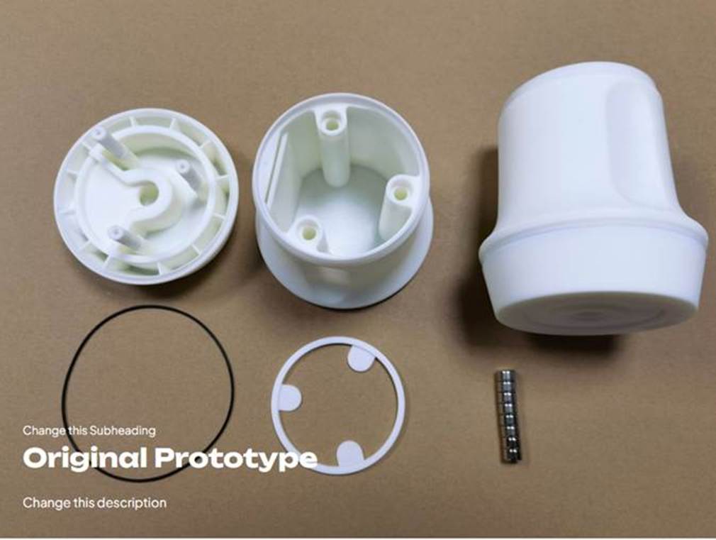
Premium Soft-Touch Plastic Components: Hookah Product Development Case Study
This case study covers the design, material, process, quality, and production decisions behind injection-molded parts with a premium soft-touch finish. A hookah brand came with a demanding brief: components that felt premium in the hand and used a specialized silicone oil spray coating, while still meeting structural and reliability requirements. The Brief and the Constraints The parts had to look and feel premium, resist handling and cleaning, and stay dimensionally accurate enough to assemble with metal and glass components. The soft-touch layer had to survive repeated contact without turning tacky or wearing through at edges. Appearance zones were tight, and the customer wanted a consistent finish across colors. Substrate and Coating Selection ABS and PC/ABS were evaluated for moldability and coating adhesion. The silicone oil spray coating was chosen for its dry, velvety feel and resistance to skin oils. Because coating performance depends on the substrate surface, gate location and flow marks had to be controlled first; a coating cannot hide a flow line, it only makes it more visible. Part and Mold Design Uniform walls reduced sink and warpage. Radii at edges prevented coating thin-out, which is where wear starts. Textures were kept shallow enough to coat evenly but deep enough to hide handling marks. Ejection was placed away from cosmetic faces, and the parting line was moved to a non-visible edge. Process Window Development Molding parameters were set for a dense, stress-free skin: moderate injection speed, adequate packing, and a mold temperature high enough to avoid frozen-in stress that later causes blisters under coating. Drying was controlled for each resin lot, since moisture shows through a thin coating as pinholes. Coating Application and Curing Parts were cleaned, masked, sprayed in controlled passes, and cured at a defined profile. Film thickness was measured on coupons, and adhesion was tested...
read more
29Oct2026
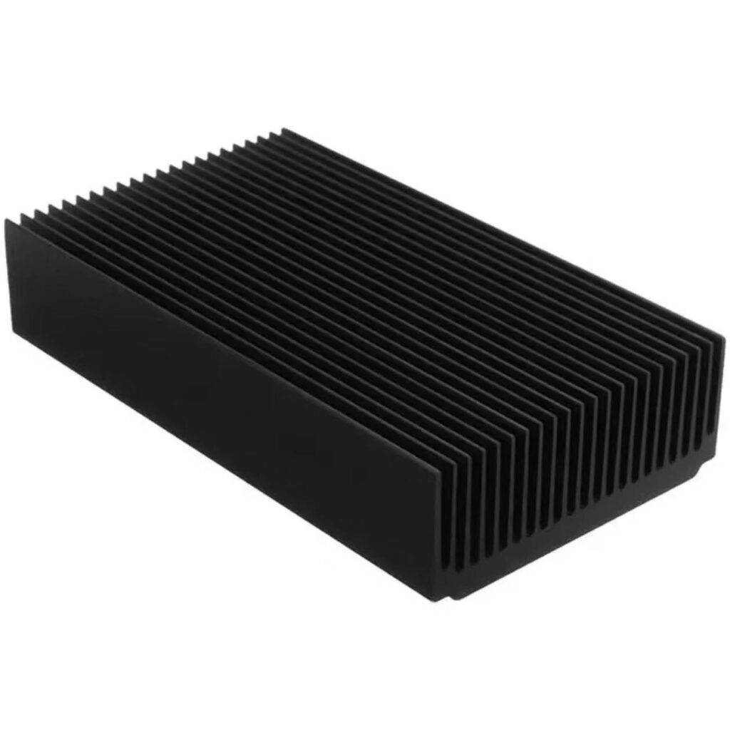
Hard Coat Anodizing: A Practical Guide to MIL-A-8625 Type III Class 2 Black Finish
For machined aluminum components, the finish is not simply cosmetic. Material, process controls, inspection criteria, and production workflow all influence how a part performs in service. When specified as MIL-A-8625 Type III, Class 2 black, the coating must provide more than a dark appearance: it becomes a functional surface system built for demanding use. What Type III Anodizing Produces Type III anodizing forms a dense, thick oxide layer significantly harder than conventional Type II coatings. Typical thickness runs from 25 to 50 microns, with hardness that improves abrasion resistance on sliding or frequently handled surfaces. Because the oxide grows into the substrate as well as outward, dimensional change is roughly half the coating thickness on each side. Alloy Selection Matters Not every aluminum grade anodizes to the same color or hardness. 6061 and 7075 are common and generally respond well, while high-silicon or high-copper casting alloys can produce dull, uneven, or dark results. 2024 tends to darken and may not hit a consistent black. Confirm the alloy before promising a cosmetic outcome, and avoid mixing alloys in one batch. Process Steps and Control Points Parts are degreased, etched, desmutted, anodized in a sulfuric acid bath at controlled temperature and current density, dyed, and sealed. Bath temperature is critical: a cold bath yields a harder, denser coating, while a warm bath grows faster but softer. Racking must carry current reliably, or contact marks and thin areas appear. Black Dye and Color Consistency Class 2 means the coating is dyed. Black is the hardest color to keep uniform, because small differences in coating thickness, alloy, and dye concentration show as variation. Boundary samples from the same alloy and batch are the practical way to control appearance, and cosmetic zones should be defined on the drawing. Sealing and Corrosion Performance Sealing closes the...
read more
29Oct2026

Injection Molding Machine Specifications: A Critical Match for Mold Transfer Projects
During a mold transfer quotation, one of the first questions should be which press will run the tool. It sounds like paperwork, but machine specifications decide whether the mold fits, runs safely, and produces the same part as before. A poor match shows up later as flash, short shots, and rework. Physical Fit: Platens, Tie Bars, and Mold Height Before design work, the mold must physically fit and install. Platen size, tie-bar spacing, mold height, and mounting details determine whether the tool can be loaded safely. A mold thicker than the available daylight cannot close, and a mold wider than the tie bars cannot enter. These fundamentals set the foundation for every later step. Clamp Tonnage and Injection Capacity The mold and machine must withstand the same internal forces. Tonnage, injection pressure, and clamp performance need to cover the projected area times cavity pressure, with margin. Too little clamp force produces flash and tool wear; too much can crush vents and damage the parting line. Shot size should sit comfortably inside the barrel capacity, typically between 20 and 80 percent of rated shot, so residence time stays healthy. Ratio of Screw Diameter to Shot Weight A small shot in a large barrel overheats and degrades; a shot near the barrel limit gives insufficient cushion. Compare the required shot weight and plasticizing rate with the recommended operating window. Thermally sensitive resins such as PC and POM tolerate narrower windows than commodity grades. Controls, Sequences, and Auxiliary Equipment Core pull sequences, valve gates, hot runner zones, ejector stroke, and robot interfaces must be available and programmable. A tool with three core pulls needs a controller with enough sequence steps. Dryer capacity, chiller flow, and temperature controller count belong in the same comparison, because an undersized chiller limits cycle time regardless of the...
read more
29Oct2026
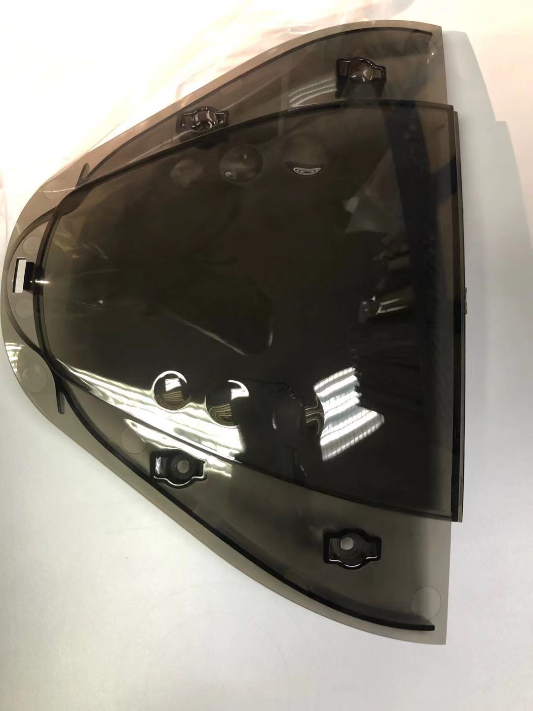
PC Translucent Molding: A Practical Guide for Design, Material, Process, and Production Teams
PC translucent injection molded parts appeal to products that must look premium while surviving real use. They do more than fill a functional role; they connect durability, light management, and user experience in one part. The key is to evaluate design, material selection, process, quality, and production planning as one connected system. Why Polycarbonate Suits Translucent Parts Polycarbonate is valued for impact strength, toughness, and heat resistance. Combined with light transmission, those properties create a strong synergy: a part can deliver visual clarity or soft translucency without giving up ruggedness. This is why pc translucent molding appears in light covers, control panels, medical housings, and equipment windows. Start With a Defined Optical Target Design should begin with the optical requirement: transmission percentage, haze, color, and whether the part is clear, frosted, or opal. Cosmetic zones, gate placement, and acceptable witness marks should be agreed at the same time. A part that is judged by eye without a written target will always be disputed at first article. Resin Grades and Additives Clarity grades differ from general grades in their additive packages. Light-diffusing grades use dispersed particles to scatter light evenly, while UV-stabilized grades resist yellowing. Consider flame-retardant or medically compliant grades only when needed, since additives often change transmission and flow. Recycled content reduces optical quality and should be limited for visible parts. Wall Design and Light Diffusion Uniform walls reduce stress and haze. Where light must spread, a textured inner surface or a stepped geometry can act as a diffuser. Sharp internal corners create stress concentrations that show as birefringence patterns under polarized light. Draft of at least one degree per side helps release without scuffing optical faces. Drying and Process Control Polycarbonate is hygroscopic. Wet resin produces splay and silver streaks that are immediately visible in a translucent part,...
read more
29Oct2026
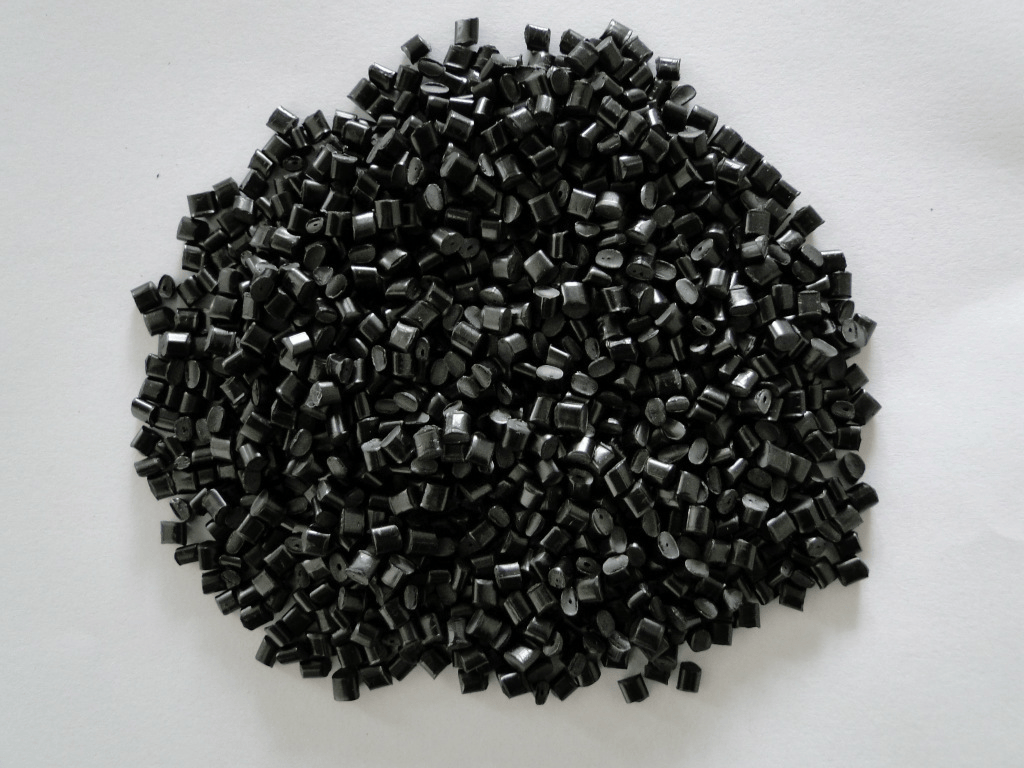
Virgin Plastic vs. Recycled Plastic in Injection Molding: What Engineers and Sourcing Teams Should Know
Teams evaluating molded components balance design intent, material, process control, quality, and economics. A common question is whether recycled plastics can reduce cost. Incentive policies and sustainability programs encourage recycled content, and the aim is reasonable. Material choice still has to follow the demands of the final part, because in injection molding material quality sets the ceiling on part performance. What Each Material Actually Is Virgin plastic is brand-new resin with known molecular weight and purity. Recycled material comes from post-industrial scrap, which is often clean and consistent, or post-consumer waste, which varies in color, contamination, and history. That distinction matters more than the label. Mechanical and Visual Differences Parts molded from virgin resin typically show a smooth finish, uniform color, and no visible impurities, with higher strength, impact resistance, and heat and aging performance. Recyclate usually loses some molecular weight through repeated heat history, which lowers impact strength and elongation. Color shifts restrict use in visible parts unless the grade is specially sorted. Processing Behavior Recycled resin may absorb more moisture, contain fines, or carry residual additives, so drying and filtration need attention. Flow can change from lot to lot, which narrows the process window and increases scrap if the controller is not adaptive. Consistency is the real cost driver, because variability forces more inspection and more rejects. Where Recyclate Fits Best Hidden structural parts where color does not matter Products with broad mechanical tolerances Non-food, non-medical applications with documented compliance Blends with virgin resin, where a stated percentage keeps properties predictable Where to Avoid Recycled Content Optical parts, sealing faces, thin walls under impact, medical or food-contact surfaces, and anything requiring long-term UV and color stability should stay on virgin material. Regrind from the same production loop is a separate case: it is usually acceptable at controlled ratios...
read more
29Oct2026
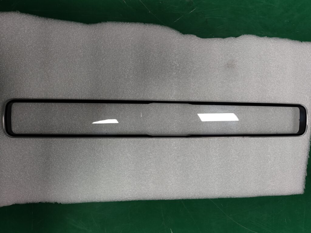
2K Overmolding vs. Standard Overmolding: Technology, Performance, and Cost Insights
Interest in 2K overmolding, often called double injection overmolding, has grown noticeably. Both routes add a second material to a part, but they do not follow the same production logic, and the difference shows up in tooling, cycle time, bonding quality, and unit cost. How Standard Overmolding Works Standard overmolding applies a second material to a preformed component. The insert may come from another molder, from an internal molding cell, or from a stocked part. It is loaded into the tool by hand, robot, or reel feed, and the overmold layer is injected over it. Tooling stays simpler, and the two processes can be optimized separately. How Two-Shot 2K Overmolding Works Two-shot molding combines both materials within one coordinated cycle. A rotating platen or indexing tool moves the first shot into the second cavity, where the second resin is injected before the first has fully cooled. Both materials fuse at the interface, which produces a stronger and cleaner bond, and no handling step is required between shots. Tooling and Equipment Requirements 2K overmolding needs an advanced tool with two cavities and a reliable index, plus a machine with two injection units and precise position control. Core pulls, hot runner zones, and cooling must be balanced across both halves. Standard overmolding uses a single-shot press and a simpler tool, but needs an insert loading system that will not damage the substrate. Performance and Bond Quality Because the second material bonds to a warm substrate, peel strength and appearance are usually better in 2K parts. The integrated cycle also reduces contamination risk from handling. Standard overmolding can match that quality with careful substrate preparation and material compatibility, but the risk of a contaminated interface is higher. Cost Comparison and Break-Even Two-shot tooling costs more and the machine requirement is higher, so low...
read more
29Oct2026
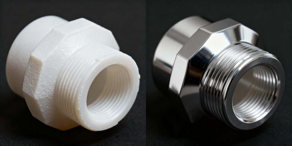
Plastic and Metal Electroplating for Durable, Premium Product Finishes
Electroplating is more than a cosmetic step. It combines design choices, substrate selection, process control, quality checks, and production planning to create surfaces that are durable, attractive, and trusted by customers. A thin metal layer on plastic or metal parts improves corrosion and wear resistance while delivering a finish that reads as premium. How the Process Works Parts pass through cleaning, etching, activation, and then one or more plating baths. For plastics, an electroless nickel strike first makes the surface conductive, after which copper, nickel, and chromium layers build thickness and appearance. For metals, plating follows machining and polishing, with rack design and current density determining uniformity. Substrate Selection for Plated Plastics ABS is the standard choice because its butadiene phase etches to create mechanical anchors for adhesion. PC/ABS blends add heat resistance, and PP can be plated with special pretreatment. Glass-filled resins often plate poorly because glass interrupts the etched surface. Design should avoid blind holes and sharp edges that concentrate current and cause burn marks. Adhesion and Appearance Control Adhesion is verified by thermal cycling and peel or pull tests, not by visual inspection alone. Appearance depends on bath chemistry, current density, and rack position; a part near the cathode edge may plate brighter than one in the center. Thickness is measured on coupons or with X-ray fluorescence, and corrosion resistance with salt spray per the agreed standard. Design Rules That Prevent Rejects Keep wall thickness uniform so warpage does not distort the plated surface Round edges and avoid deep recesses that trap chemistry Provide rack contact points on non-cosmetic surfaces Specify the finish standard, thickness, and salt-spray hours Agree acceptance lighting and a boundary sample before production Quality and Production Planning Plating lines run on bath life, so scheduling should account for maintenance and analysis cycles. Keep...
read more
29Oct2026

Injection Molding Cycle Time: A Practical Guide to Output and Profitability
In manufacturing, "cycle time" is a familiar phrase, but in injection molding it deserves close attention. It represents the total time needed to complete one full production cycle and serves as the operational heartbeat of the molding process. Design, material, process, quality, and production decisions all influence this critical metric. How to Measure Injection Molding Cycle Time The clearest way to picture cycle time is to watch the interval between finished parts. It is the time from the moment one completed part is removed from the mold to the moment the next identical part is removed. In an automated molding cell, this rhythm is easy to see: a robot arm enters the mold area, extracts a part, retracts, and the machine prepares for the next shot. The time between two consecutive part removals is the cycle time. The Five Stages of a Cycle To optimize cycle time, break the full cycle into its main stages: clamping, injection and packing, cooling, mold opening, and ejection. Expressed as a formula, Cycle Time = Clamping Time + Injection/Packing Time + Cooling Time + Opening Time + Ejection Time. Each stage contributes to the total, so improvements must be evaluated across the entire process rather than in isolation. Cycle Time and Production Capacity Cycle time has a direct effect on production capacity. The relationship can be stated simply: Hourly Production Output = 3600 seconds / Cycle Time in seconds. This formula is fundamental to capacity planning. A faster cycle raises output from the same equipment and workforce. In one illustrative case, a 6.7% increase in output was achieved without adding a machine or an operator. Over a month or a year, those saved seconds compound into meaningful gains in capacity and profitability. Where the Seconds Actually Go Cooling usually dominates the cycle, often consuming...
read more
28Oct2026
Reverse Engineering as a Strategic Partnership: Replicate, Improve, Manufacture
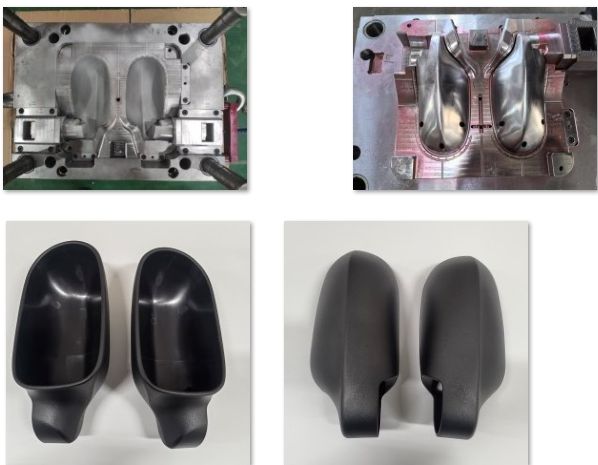
Reverse engineering requests often begin simply: a client sends a sample and asks, "Can you make this?" Advanced 3D scanning can capture geometry with high accuracy, but a successful project should not stop at duplication. The stronger goal is to understand the original, correct its weaknesses, and create a version that is more competitive in the market. Why Reverse Engineering Is More Than Scanning The common misconception is that a factory's role is only to scan and produce. In practice, the most valuable contribution is strategic partnership—especially teaching manufacturability. Design, material, process, quality, and production considerations should be evaluated from the beginning, so the final part is not merely a copy but a product built for efficient molding. Pillar One: Interpreting Scan Data A 3D scanner produces a point cloud, a digital shell of the sample. Engineers must determine not only what shape the data shows but why that shape exists. They convert raw scan information into a production-ready 3D model, adding draft angles, uniform wall thickness, and appropriate tolerances that the original sample may not have. This makes the part suitable for injection molding from day one. Pillar Two: A Disciplined Workflow A clear, mutually respected workflow is the strongest predictor of on-time delivery and budget control. Client participation and timely approvals at each gate are essential, not merely formal. As a partner, the supplier stays transparent and rigorous about the process to protect the client's investment. Pillar Three: Translating Design Into Manufacturing A design is only truly strong if it can be produced efficiently and reliably. The critical questions clients may not have considered usually sit in tooling: can this undercut be released, will this wall fill, does this tolerance survive shrinkage? Answering them during modeling avoids rework later, when the tool already exists. When Reverse Engineering Makes...
read more
28Oct2026
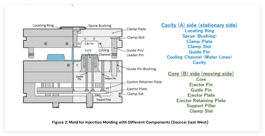
Injection Mold Fundamentals: Design, Manufacturing, and Maintenance
Injection molding depends on the mold, often called a tool or die, to turn a part design into repeatable production. The tool is a precision negative of the finished component, so its cavity and related features directly govern shape, dimensions, surface quality, and consistency. What an Injection Mold Contains A typical tool stacks a top clamp plate, cavity plate, core plate, support plate, spacer, and ejector housing. Leader pins align the halves, the sprue and runner deliver melt, and the cooling system removes heat. Ejection, venting, and any sliders or lifters complete the picture. Each element carries a tolerance that shows up in the finished part. Steel Versus Aluminum Most production molds use high-strength steel because it holds dimensions over hundreds of thousands of cycles and tolerates abrasive fillers. Aluminum tools machine quickly and suit prototypes and low volumes, but they wear faster and are easier to dent. The choice should follow volume, resin abrasiveness, and tolerance rather than habit. How the Cycle Uses the Tool Molten plastic is forced under pressure into the cavity. After the plastic cools and solidifies, the ejection system releases the finished part. Fill, pack, cool, and eject each depend on the tool: gate size sets fill, vent depth sets pack, cooling layout sets cycle time, and ejector balance sets part quality at release. Design Decisions That Matter Wall thickness uniformity reduces sink and warp. Draft allows release without scuffing. Ribs thinner than the nominal wall avoid sink on the visible face. Gate location should fill thick sections last and avoid weld lines on cosmetic or structural areas. Cooling channels belong close to the surface, following heat concentration rather than an even grid. Maintenance Keeps the Tool Honest A well-built mold is only as good as its maintenance. Schedule cleaning and inspection by shot count,...
read more