


28Oct2026
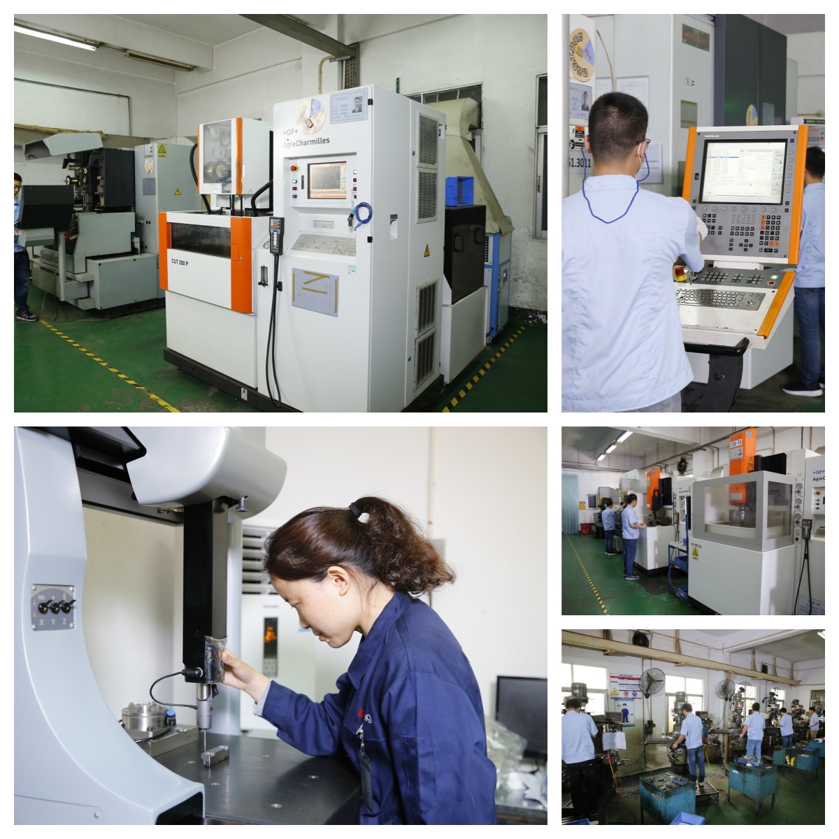
China Manufacturing Partner for Precision Molds, Injection Molding, and Assembly
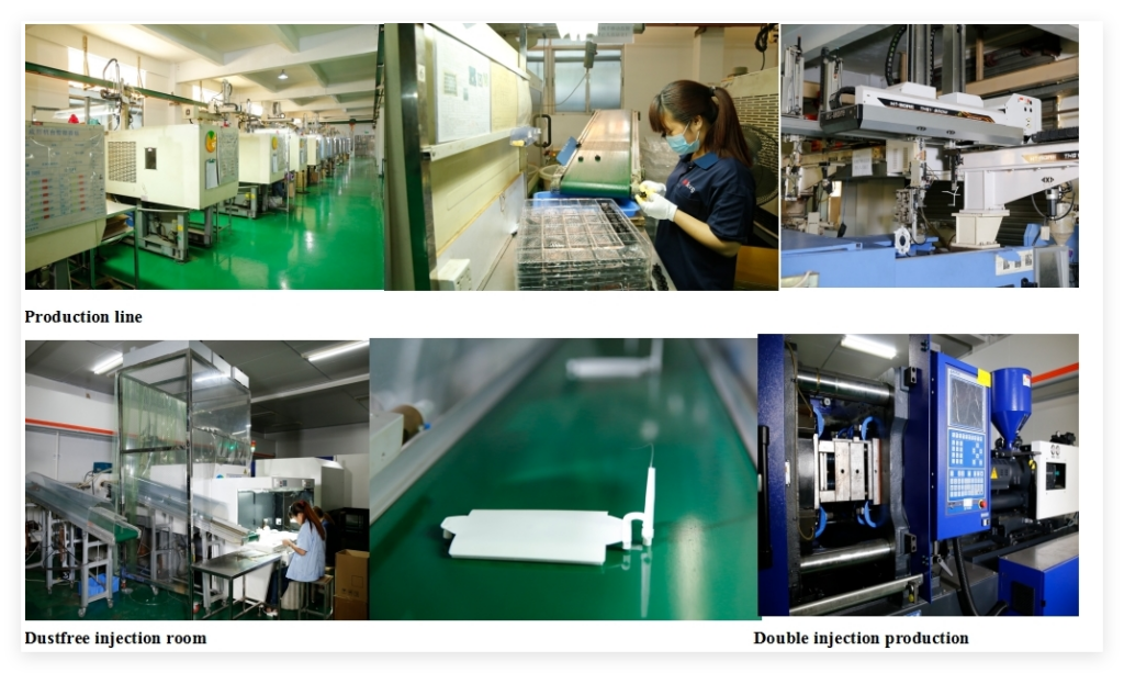
Engineers and sourcing teams evaluating a China manufacturing partner need a clear view of component design, material selection, tooling strategy, molding process, quality systems, and production scale. A partner that covers all six reduces hand-offs, shortens lead time, and keeps accountability in one place—especially for programs that combine molds, molding, and assembly. What a China Manufacturing Partner Should Cover Rilong has built its service around those decision points for more than three decades, covering mold design, development, and production for plastic and rubber molds and products. The scope matters: when tooling, molding, finishing, and assembly sit under one roof, dimensional issues are resolved inside the same quality system instead of being argued across suppliers. Molding Capability: Over-Molding and Multi-Material The molding portfolio includes hard and soft plastic over-molding, soft plastic and metal over-molding, double injection, LSR-to-plastic and LSR-to-LSR over-molding, and membrane keypads. These capabilities help product teams integrate rigid structures, soft-touch surfaces, sealing features, ergonomic forms, and multi-material aesthetics into a more efficient production plan. Tooling Equipment and Precision For tooling, the company uses eight advanced CNC machines from Charmilles, Seiki, and Mitsubishi; seven EDM systems from Charmilles and Sodick; and two WEDM systems from Charmilles and Sodick. Grinding, milling, manual grinding, CMM inspection, and 2D testing support high-precision injection molding for complex geometries and tight tolerances, with stable process control for low- and high-volume projects. Process Breadth Beyond Injection Molding Double injection molding allows different materials or colors to be formed in one integrated cycle, strengthening bonding, improving functionality, and expanding design freedom. Over-molding soft plastic onto hard plastic or metal produces durable, ergonomic, reliable components for consumer electronics, industrial controls, medical devices, and automotive applications. The company also supplies rubber parts with strong resilience, anti-aging behavior, and chemical resistance, using EPDM, NBR, silicone rubber, and other materials selected...
read more
28Oct2026
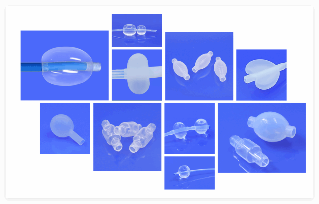
Medical Silicone Molding: A Guide for Engineers and Sourcing Teams
Medical silicone molding brings together five connected decisions: component and mold design, material choice, molding process, quality control, and production readiness. For engineers and sourcing teams, these choices directly affect patient safety, device reliability, manufacturing yield, and time to market. Why Material Choice Comes First Material selection is central to medical device safety and performance. Medical-grade silicone raw materials are rigorously selected and supported by comprehensive biocompatibility testing. This helps minimize irritation and allergic reaction risks and provides a dependable foundation for implants, wearable devices, and products with long-term body contact. A part that performs well in a general-purpose grade may fail the same application once biocompatibility, extractables, or sterilization requirements are applied. Properties That Matter in Medical Devices Silicone's softness and elasticity allow medical components to fit complex anatomical shapes while maintaining resilience. Devices can conform to body curves more comfortably without losing functional stability. Chemical resistance is equally important in hospitals and laboratories, where repeated exposure to disinfectants and other chemicals is common. Medical silicone maintains stability through many of these exposures, helping preserve performance after repeated sterilization and use. Long-term durability is another critical requirement. Medical silicone is designed for strong abrasion and oxidation resistance, resisting aging, hardening, and cracking during extended use. This supports consistent device performance across the product lifecycle and helps reduce failure rates. Choosing Between LSR Injection and Compression Molding Liquid silicone rubber injection molding suits high-volume, precision parts with tight tolerances and thin walls, because metering, curing, and demolding are automated. Compression molding remains practical for larger, lower-volume parts and for designs where tooling cost dominates. The decision affects cycle time, flash, dimensional consistency, and how easily the process can be validated. Both routes require clean-room discipline and material handling controls when the device is intended for clinical use. Mold and Part...
read more
28Oct2026
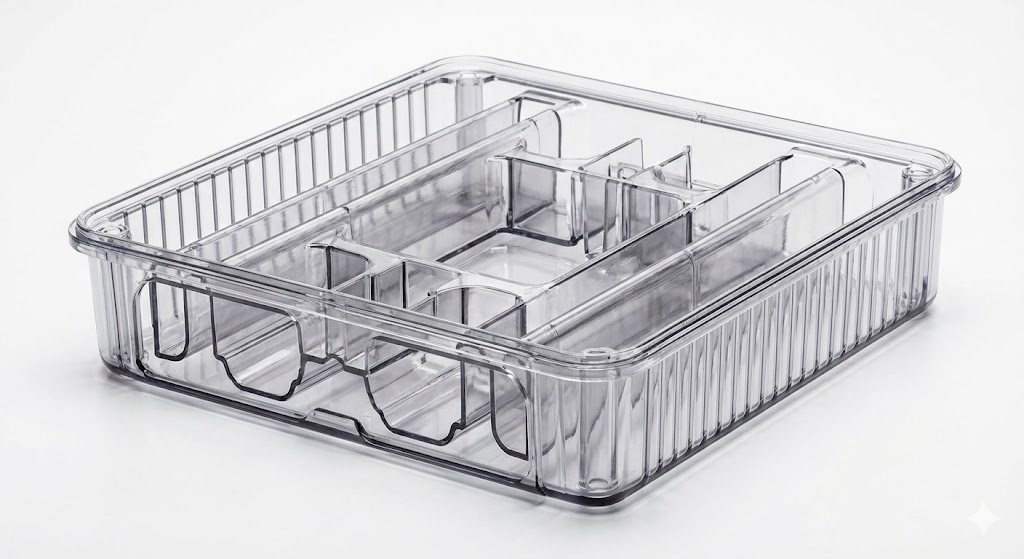
Hollow Injection-Molded Parts: Design, Tooling, and Production Guidance
Hollow injection molded parts demand early engineering attention because internal cavities and unsupported sections make them difficult to manufacture. Common risks include warpage, uneven shrinkage, sink marks, surface waviness, and dimensional instability. These defects can interfere with assembly, affect sealing performance, and reduce product lifespan, so design, material, process, and quality have to be reviewed before tooling begins. Why Hollow Injection Molded Parts Are Hard to Mold A hollow part has walls on both sides of an empty space, and every wall shrinks as it cools. If the inner and outer walls differ in thickness, the part pulls in different directions and warps. If a thick section sits next to a thin one, the thick area stays molten longer, creating sink marks or internal voids. The geometry itself sets the difficulty, which is why hollow injection molded parts need a design review before steel is cut. Design Rules for Stable Hollow Sections Keep wall thickness uniform: variation above roughly 20% invites warpage and sink Use ribs instead of thick walls: ribs add stiffness without adding mass Add draft on every vertical face: typically 1° or more to ease ejection Round internal corners: sharp corners concentrate stress and restrict flow Design the opening deliberately: the core that forms the cavity must be able to withdraw Tooling Considerations The core that creates the hollow space drives much of the tool design. Long, slender cores need cooling and support, or they deflect under injection pressure and produce wall-thickness variation. Gate position matters as well: feeding into a thin wall can freeze off before the cavity fills, while feeding into a thick section can cause overpacking. Where the hollow space is closed, collapsible cores or sliding mechanisms may be required. Process Control for Even Shrinkage Molding parameters should favor uniform cooling. Moderate injection speed,...
read more
28Oct2026
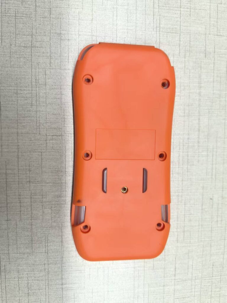
Silicone vs. TPE Handle Covers: A Practical Guide for Overmolding Projects
On tool handles, sports equipment, and consumer devices, the cover material decides tactile feel, service life, and how the product is perceived. Silicone is often assumed to be the default soft-touch choice, yet TPE and TPU grades are increasingly specified for advanced designs because their performance profile differs in useful ways. How the Two Materials Differ Silicone is a thermoset that cures into a flexible, heat-resistant layer with a dry, silky feel. TPE is a thermoplastic elastomer that melts and bonds to a compatible substrate during overmolding. That processing difference drives tooling, bonding, recyclability, and cost. Tactile Feel and Friction Silicone feels smooth and slightly tacky, and it stays consistent across a wide temperature range. TPE can be formulated from velvety to rubbery, and its coefficient of friction can be tuned with fillers and surface texture. For a grip that must feel secure with oily hands, a textured TPE often wins; for a soft, premium touch, silicone is hard to match. Durability and Environmental Resistance Silicone tolerates heat, UV, and ozone well and stays flexible from about -60°C to 200°C. TPE has a narrower service window and can soften or degrade with certain oils and solvents, though specialty grades improve chemical resistance considerably. For outdoor equipment, specify UV-stabilized grades of either material and validate with accelerated weathering. Bonding and Design Rules Overmolded TPE bonds chemically to PP, PC/ABS, and PA when the substrate is designed with mechanical interlocks and the materials are compatible. Silicone needs primer or a self-bonding grade, and its bond is often mechanical plus chemical. In both cases, avoid sharp edges at the bond line, keep wall thickness uniform, and allow for differential shrinkage. Processing and Tooling LSR molding uses a cold runner and heated mold with fast cycles and low scrap. TPE overmolding uses conventional injection...
read more
28Oct2026
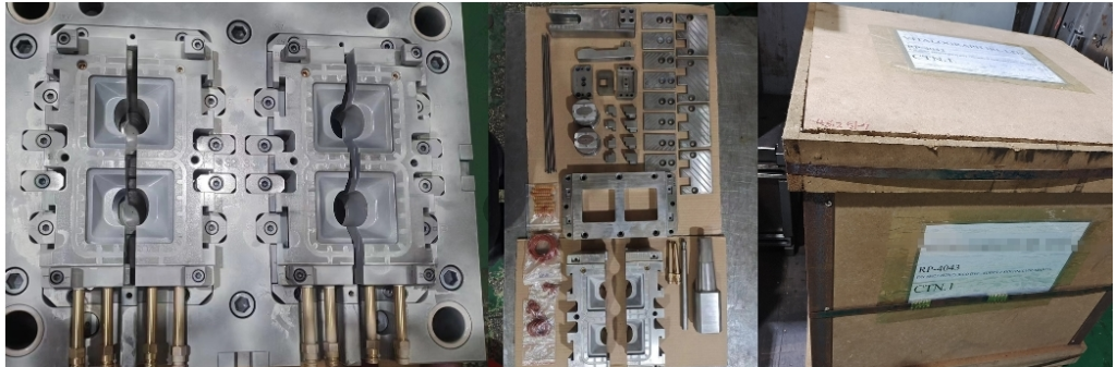
Transfer-Ready Injection Molds: Design, Quality, and Production Considerations
Moving a tool between regions is a project, not a shipment. Transfer-ready injection molds are judged by whether they run the same part, at the same quality, on a different press and in a different plant. Passing one trial is not proof; stability, maintainability, and documentation decide the outcome. What Makes a Mold Transfer-Ready A transfer-ready tool has a clean design history, verified steel condition, complete drawings, and a process record that another plant can reproduce. It should also be compatible with the target machine and with local standards for safety, cooling supply, and lifting. Buyers who plan a transfer later should specify these items at the original order. Design and Documentation Review Start with the 2D and 3D tool drawings, the part drawing with tolerance and cosmetic criteria, and the mold structure drawing. Check the parting line, ejection, cooling layout, and any actions such as sliders or lifters. Confirm that the drawing set matches the physical tool, because undocumented changes made during debugging are the most common cause of transfer failure. Machine Compatibility Platen size, tie-bar spacing, mold height, daylight, ejector pattern, and nozzle radius must match the receiving press. Tonnage and shot size need margin. Core pull circuits, hot runner zones, and sensor connectors must be available in the new plant. A mold that requires a special controller may still be transferable, but only if that equipment is included in the plan. Condition Assessment and Refurbishment Inspect cavity and core surfaces for wear, erosion at gates, and corrosion in cooling channels. Measure critical dimensions on a sample shot, and check that cooling flow and pressure drop are within expectation. Refurbishment before shipping is cheaper than a stalled project after arrival. Quality Records and Process Data Transfer-ready injection molds should travel with a process sheet, first-article report, material certificates,...
read more
28Oct2026

Why an Experienced Overseas Mold Maker Reduces Sourcing Risk
Choosing an overseas mold maker is a decision about risk as much as about price. A quotation tells you what a tool costs; it does not tell you whether the design review will catch a wall thickness problem, whether the steel matches the resin, or whether the same part will arrive in month twelve as in month one. Experience is the proxy most buyers use for those answers, and it should be examined rather than assumed. What Experience Actually Buys A shop that has built thousands of tools has seen the failure modes that a new supplier only reads about: gate freeze-off on a thin wall, a slider that galls after two hundred thousand cycles, a texture that cannot be polished out of a tight corner. That knowledge enters the project during DFM review, which is the cheapest stage to change anything. Design Review as the First Control Ask what the supplier will question before quoting. Draft, uniform wall, weld line location, gate position in cosmetic zones, ejection marks, and tolerance stack against assembly are the basics. A supplier that only confirms the drawing is a machine shop; one that raises issues is a mold maker. Certification and Quality Systems ISO 9001 covers general quality management, IATF 16949 adds automotive process discipline, and ISO 13485 applies to medical devices. The certificate matters less than the records behind it: inspection plans, calibration logs, material certificates, and traceability from steel lot to shipped tool. Equipment That Supports Tolerance Mirror EDM, slow wire cutting, and high-speed machining determine what the shop can hold without hand work. A supplier with the right equipment can cut a shut-off to a few micrometers and leave a polish that needs no benching. Without it, tolerances depend on the skill of an individual rather than on a repeatable...
read more
28Oct2026
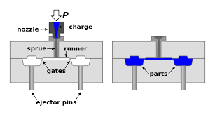
Optimizing Injection Mold Gate Design to Prevent Sink Marks
Sink marks appear as shallow dents on molded surfaces, usually above ribs, bosses, or thick sections. The cause is simple: those areas cool last and shrink after the gate has sealed, so no melt is available to compensate. Injection mold gate design therefore decides whether packing can reach the thick area in time. Why Gate Design Controls Sink Marks Packing pressure only works while the gate is open and the thick section is still molten. If the gate freezes early, the cavity is isolated and shrinkage becomes a visible dent. A gate that is too small, too far from the thick region, or badly placed turns a moldable part into a cosmetic reject, no matter how the press is tuned. Gate Types and Their Behavior Edge gate: simple and cheap, but freezes early and leaves a mark that needs trimming Fan and film gate: spread flow for flat parts and reduce orientation, at the cost of trimming Hot runner / valve gate: holds packing pressure longer and leaves minimal vestige Direct sprue gate: good for thick single-cavity parts but leaves a large witness mark Submarine gate: automatic degating for high volume, with limited size Sizing the Gate for Packing Gate cross-section should be sized from the part volume and wall thickness, not from habit. As a working rule, the gate thickness is often 50 to 70 percent of the wall it feeds, with depth increasing for thick sections. Shear rate at the gate must stay within the resin supplier's window; too high causes jetting and blush, too low causes hesitation and short shots. Location Rules That Reduce Sink Place the gate so flow reaches the thickest section last, allowing packing to continue there. Avoid gating into a thin wall that feeds a thick rib, because the thin wall freezes first....
read more
13Oct2026
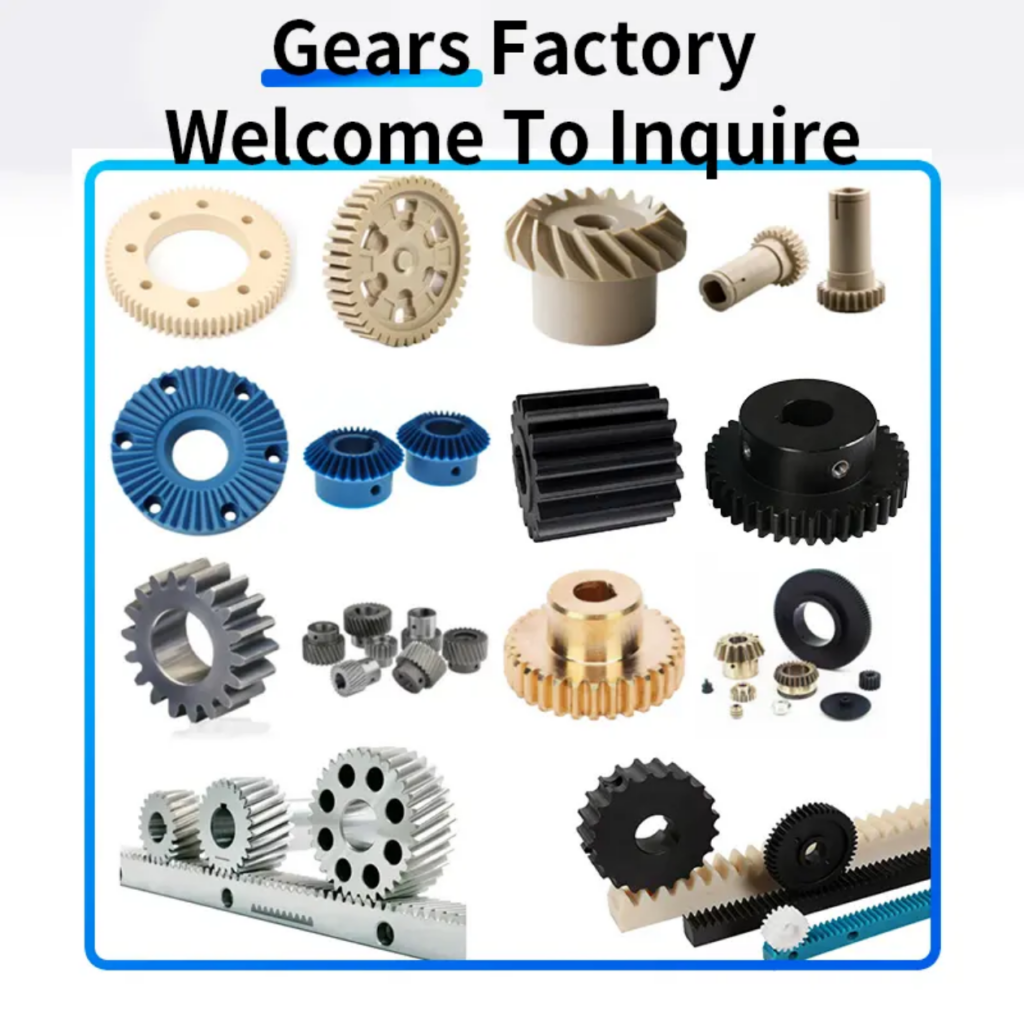
Plastic Gear Injection Molding: Design, Materials, and Quality Guide
Plastic gears replace metal in many assemblies because they run quieter, resist corrosion, and can be molded with hubs and shafts in one part. The trade-off is that tooth accuracy, wear, and strength depend heavily on tooling and material choices made long before the first sample. Material Selection for Gears POM (acetal) is the default for precision gears because of low friction, good fatigue resistance, and dimensional stability. PA66 offers higher strength and heat resistance but absorbs moisture, which changes tooth dimensions. PBT and PEEK extend temperature and chemical limits at higher cost. Glass-filled grades increase stiffness but also increase wear on mating metal parts, so the pair should be evaluated together. Tooth Accuracy and Shrinkage Gear quality depends on tooth profile, spacing, and concentricity. Shrinkage varies with tooth thickness and flow direction, so a mold cut to nominal dimensions will not produce nominal teeth. Tool correction after the first sample is normal: measure the tooth profile, calculate the deviation, and adjust the electrode or wire path. Gate Location and Weld Lines A gate placed at the hub gives radial flow and reasonable symmetry, but creates a weld line opposite the gate. If that weld line lands on a loaded tooth, the gear fails there. Multi-point gating or a ring gate distributes flow and moves the weld away from the contact zone, at the cost of tooling complexity. Design Rules Keep tooth thickness uniform to reduce warp Use a hub with a generous fillet at the web to spread load Provide draft on the tooth flank for clean ejection Allow clearance for moisture expansion in PA gears Specify the quality grade and the inspection method on the drawing Wear and Lubrication Plastic gears usually run dry or with light grease. The combination of materials matters: POM against POM wears well,...
read more
13Oct2026
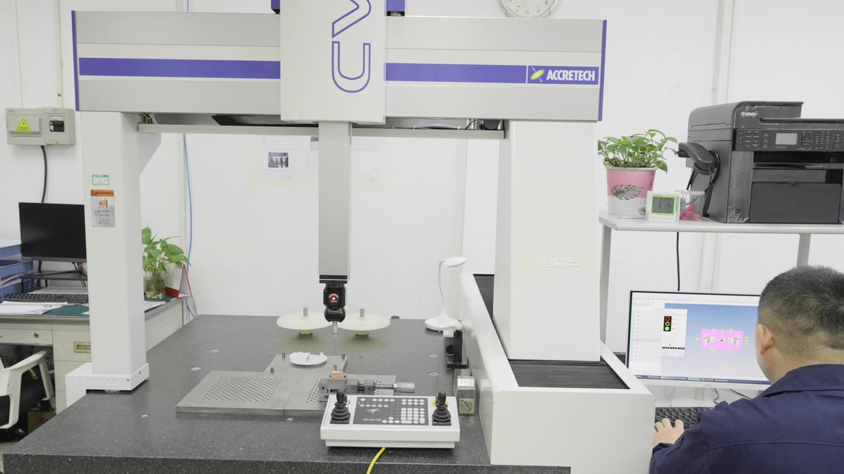
CMM Inspection: Precision Metrology for Manufacturing Excellence
Coordinate measuring machines turn a physical part into verified data. For molded and machined components, CMM inspection confirms that dimensions, form, and position meet the drawing before parts reach assembly or a customer. The value depends on how the measurement is planned, not just on the machine's accuracy specification. What a CMM Measures A CMM probes discrete points on a surface and calculates geometry from them: diameters, distances, angles, flatness, position, and profile. Because it works in three dimensions, it verifies relationships that calipers and micrometers cannot, such as true position of a hole pattern relative to datums. Machine Types and Their Fit Bridge and gantry machines suit large or heavy parts; cantilever designs suit small, high-accuracy work. Scanning heads collect dense point clouds for form analysis, while touch-trigger probing is faster for simple features. Vision and multisensor systems add optical measurement for small features and soft surfaces. Alignment and Datum Strategy Measurement begins with alignment to the drawing datums. A poor alignment shifts every result, so the setup should mirror the drawing's datum scheme rather than whatever is convenient on the table. Fixturing that holds the part without distortion matters as much as the machine. Probe Strategy and Uncertainty The number and distribution of points affect the calculated result. A circle measured with four points may not reveal lobing; more points or a scan does. Probe tip size, stylus length, and approach speed all contribute to uncertainty, which should be stated when a tolerance is tight relative to machine capability. Reporting That People Can Use A useful report lists each characteristic, nominal, tolerance, measured value, and deviation, with the instrument and the program identified. Color-coded deviation plots help a toolmaker see where material must move. Reports without measured values, only pass or fail marks, cannot support corrective action. Where...
read more
13Oct2026
Existing Mold Transfer and New Mold Development | Rilong Precision Mold
When a product needs to move to a new supplier, the first question is whether to transfer the existing tool or build a new one. The two routes differ in cost, schedule, and risk, and the right answer depends on tool condition, design maturity, and volume expectations. What a Transfer Involves A transfer moves the physical tool to a new plant, then re-establishes the process on a different press. Work includes condition assessment, shipping, fitting, water and electrical hookup, trials, and dimensional approval. The part design does not change, so the customer keeps existing approvals. What New Development Involves A new tool starts from the part drawing, with DFM review, structure design, steel selection, machining, trials, and validation. The advantage is a clean design that can correct known weaknesses, add cavitation, or improve cooling. The disadvantage is cost and schedule. Assessing an Existing Tool Before committing to a transfer, inspect cavity and core surfaces for wear and erosion, measure critical dimensions on a sample shot, and check cooling flow and pressure drop. Review the drawing set against the physical tool, because undocumented changes made during debugging are the most common cause of a failed transfer. Cost and Lead Time Comparison A transfer typically costs a fraction of a new tool and can be completed in weeks, but it inherits the original design's limitations. New development costs more and takes longer, yet it can raise cavitation, shorten cycle, and fix a chronic defect. At high volume, the new tool often pays back through cycle time and scrap. Risk Factors Transfer: unknown tool history, machine mismatch, missing documentation New tool: schedule risk, design changes needing revalidation, higher upfront cost Making the Decision Transfer when the tool is in good condition, the design is stable, volume is moderate, and speed matters. Develop new...
read more