

30Oct2026

Manufacturing Quality Control for Precision Plastic Injection Molding
For precision plastic programs, manufacturing quality control is not a final inspection step. It is a system of checks that runs from drawing review to shipment, catching variation before it becomes scrap. Engineers and sourcing teams should look at how a supplier plans inspection, controls processes, documents results, and responds when something drifts. Why Manufacturing Quality Control Matters in Injection Molding Injection molding produces parts with tight tolerances, cosmetic expectations, and functional demands that vary with the application. A single unstable process can create short shots, warpage, flash, or dimensional drift across a production run. Manufacturing quality control makes that variation visible while the process is still running, so adjustments happen before parts reach the customer. The Four Pillars of Quality Control A practical framework covers four areas: Design inputs: clear drawings, GD&T, critical features, and acceptance criteria Incoming materials: resin certificates, drying records, and batch traceability In-process control: first-article inspection, patrol checks, and machine parameter monitoring Final verification: dimensional reports, functional tests, and packaging checks How to Build a Control Plan A control plan lists every feature that matters and states how it will be checked. For each critical dimension, it defines the measuring instrument, the sampling frequency, the reaction plan, and the person responsible. The plan should also cover cosmetic zones and functional tests such as assembly fit or leak checks. When the plan is agreed before tooling release, inspection effort follows risk instead of habit, and shop-floor decisions no longer depend on individual judgment. In-Process Inspection and Measurement First-article inspection confirms that the tool and process meet the drawing before volume production starts. Patrol inspection then samples parts at defined intervals, measuring critical dimensions with calipers, micrometers, gauges, or a coordinate measuring machine (CMM). Visual standards cover flash, flow marks, sink marks, and gate cosmetics. When a...
read more
30Oct2026
LSR Double Injection Molding: Design, Material, Process, and Quality Guide
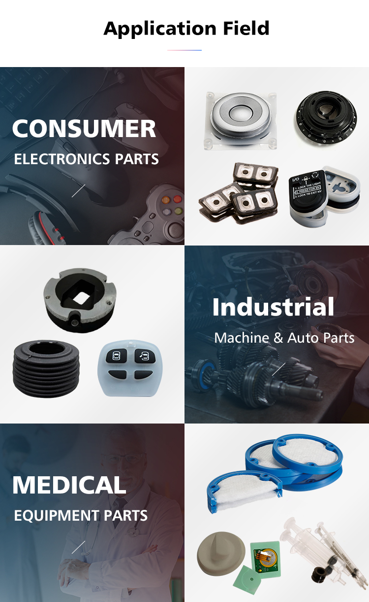
LSR double injection molding combines two very different materials in a single cycle: a liquid silicone rubber that cures by addition reaction, and a rigid thermoplastic that melts and freezes. The result is a part with a soft, sealed interface that needs no adhesive and no assembly step. Getting there requires the tool, the dosing system, and the substrate to be planned together. Why Choose LSR Double Injection Molding Attaching a silicone gasket to a housing with adhesive adds a process, a cure time, and a failure mode. When the seal is molded in place, the bond forms while the silicone is still liquid, so it wets the substrate surface and cures against it. Parts come off the press sealed, and the assembly line loses a station instead of gaining one. Material Behavior That Shapes the Design LSR shrinks only about 0.1 to 0.3 percent, far less than most thermoplastics, so silicone dimensions are stable but the substrate around them is not. A PA66 housing that grows with moisture can stress a bonded seal. Substrate choice should consider heat deflection temperature, chemical compatibility, and how the plastic behaves after the silicone cure cycle at 150 to 180 degrees Celsius. Bonding to the Thermoplastic Substrate Adhesion depends on the plastic: PA, PBT, PPS, and some PC blends bond well, while polyolefins need a primer or a mechanical interlock. Undercuts, dovetails, and through-holes give the silicone a physical grip that survives thermal cycling even when chemical bonding is modest. Designing both a bond and a lock is the most reliable approach for parts that see repeated sterilization or vibration. Tool Design for Two-Shot LSR The mold usually runs a rotating or sliding core so the plastic shot and the silicone shot share one tool. The plastic cavity is vented and cooled like...
read more
30Oct2026
Custom TPE Fiber Optic Connector Boots: Safety, Durability, and Precision Manufacturing
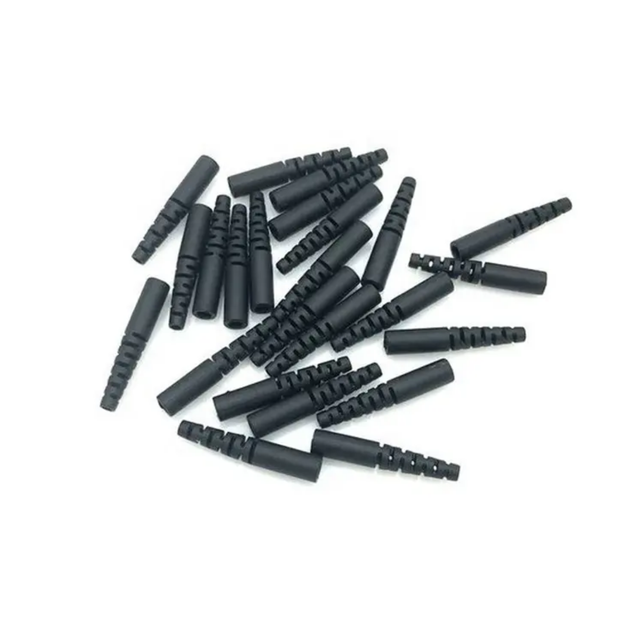
Fiber optic connectors carry signals at tolerances measured in microns, yet the cable they attach to is handled roughly in the field. The boot is the part that absorbs that handling. A well-designed TPE boot protects the fiber from bending below its minimum radius while keeping the connector seated and sealed. What the Boot Must Do The boot provides strain relief, limits bend radius, and seals the connector body against dust and moisture. It must also stay flexible across temperature so it does not crack in cold or soften in heat. In data centers and outdoor cabinets, those requirements run simultaneously. Why TPE Fits the Application Thermoplastic elastomers offer a tunable hardness range, good tear resistance, and clean overmolding onto connector bodies. They can be formulated for low smoke and halogen-free compliance, which matters in enclosed equipment. Compared with silicone, TPE bonds more easily to engineering plastics and costs less at volume. Design Rules for Bend Relief Provide a gradual taper rather than a sharp step at the connector Keep the boot length long enough to control the bend radius Add internal ribs or a bellows section for flexibility Avoid sharp internal corners that concentrate stress Specify retention force so the boot stays seated during pull Material Grade Selection Shore hardness usually falls between 60A and 85A for cable boots. Softer grades flex more but can tear at the connector interface; harder grades protect the fiber better but resist routing. Flame-retardant and low-smoke grades are specified for indoor enclosures, and UV-stabilized grades for outdoor installations. Overmolding and Bonding The boot is often overmolded directly onto the connector body or the cable jacket. Bond strength depends on substrate compatibility and surface preparation. Where the boot must be removable, a mechanical retention feature replaces chemical bonding. Validation Testing Tests typically include bend...
read more
30Oct2026
One-Stop Manufacturing Services: From Design to Delivery with RiLong Precision Mold
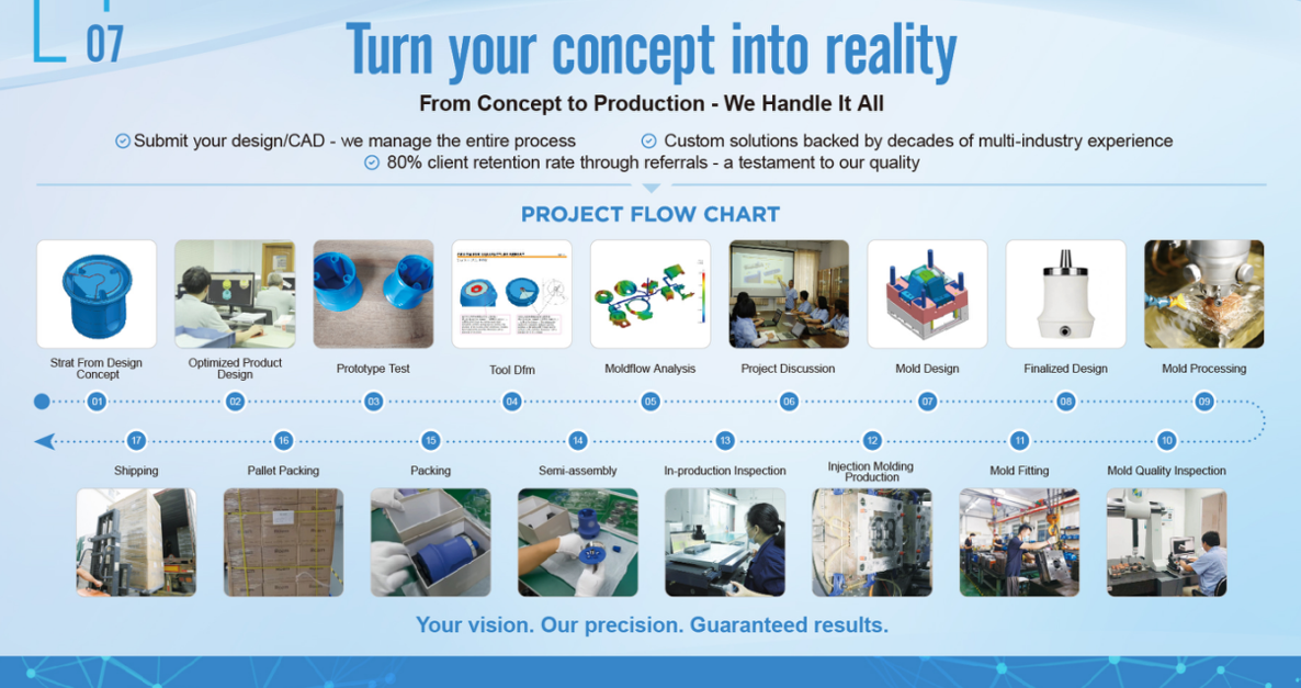
Managing design, prototyping, manufacturing, and finishing across separate suppliers creates delays, miscommunication, and inconsistent results. Bringing the work under one roof reduces handoffs and fixes accountability, but only when the internal checkpoints are as strict as the ones a buyer would apply between vendors. Why Fragmentation Costs More Than It Seems Every handoff adds a specification gap. The toolmaker interprets the drawing, the molder interprets the tool, and the finisher interprets the cosmetic standard. When a defect appears, three parties point at each other while the schedule slips. A single owner collapses that loop. Design Review as the First Gate The design should be reviewed for manufacturability so that features, tolerances, and assembly needs are confirmed before tooling. Draft, wall thickness, gate location, ejection, and cosmetic zones are checked against the chosen process. Open questions are closed while changes are still inexpensive. Tooling and Sampling Tool build follows the approved structure drawing, with in-process checks on cavity dimensions and fit. First trial samples are measured against the drawing, and the corrective list drives the next iteration. Approval is based on data and boundary samples, not on a verbal impression. Molding and Process Control Once the process window is validated, production runs against a documented parameter set with monitoring on fill, pack, and cooling. Deviations are recorded, and scrap is reviewed rather than hidden. Material certificates and lot traceability connect the finished part to its inputs. Finishing, Assembly, and Delivery Secondary operations such as painting, laser marking, plating, and ultrasonic welding are scheduled with the same discipline. Assembly stations verify fit and function, and packaging is specified so parts arrive undamaged. A delivery plan that includes buffer stock protects the customer from a single process hiccup. Frequently Asked Questions Does one-stop manufacturing cost more? Unit prices can be similar, and total...
read more
30Oct2026
How Smart Injection Mold Design Reduces Tooling and Production Costs
Tooling and part cost are usually treated as separate negotiations, but both are set by the same early decisions. A mold designed with cost in mind runs faster, needs fewer repairs, and produces less scrap. The savings do not come from cutting quality; they come from removing unnecessary complexity. Simplify Before Optimizing The cheapest feature is the one that does not exist. Before adding a slider or a lifter, ask whether the function can be achieved with a redesign: a snap instead of a screw boss, a cored hole instead of a side action, a parting line moved to a hidden edge. Each action removed saves machining, fitting, maintenance, and cycle time. Cooling Design Pays Back Fastest Cooling determines cycle time, and cycle time repeats on every shot. Conformal or baffled cooling near thick sections shortens the cycle and reduces warpage. Balanced circuits with individual flow control prevent one cavity from running hot. The extra machining cost is recovered within weeks at volume. Standard Components Mold bases, ejector pins, springs, hot runner nozzles, and cooling fittings from standard catalogs cost less and ship faster than custom parts. Standardization also simplifies maintenance, because replacements are available locally. Custom design effort should focus on the cavity and core, where it changes part quality. Cavitation and Press Match More cavities lower machine cost per part but raise tooling cost and balance risk. The right number follows annual volume and the available press. A four-cavity tool matched to a well-utilized press often beats an eight-cavity tool that runs half empty. Gating and Runner Strategy Hot runners cut scrap and shorten cycle on engineering resins, but add cost and maintenance. Cold runners suit short runs and frequent color changes. The decision should follow volume, resin cost, and color change frequency rather than preference. Maintenance Access...
read more
30Oct2026
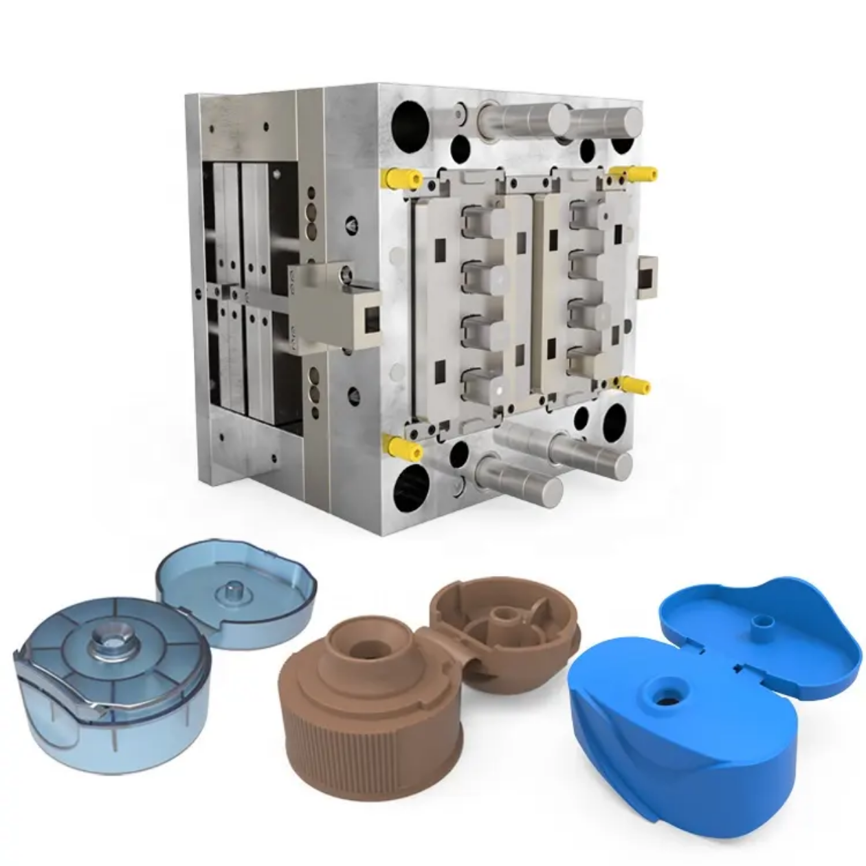
Collapsible Core Molds: A Practical Guide for Complex Part Manufacturing
Internal threads, snap rings, and re-entrant features are difficult to mold because the part cannot simply be pushed off a solid core. Collapsible core molds solve this by contracting before ejection, so the undercut clears without drag. The approach opens designs that would otherwise need assembly or a secondary machining step. How the Core Collapses The core is built from segments arranged around a center pin. During injection the segments are expanded against the pin, forming the undercut. Before ejection the pin retracts and the segments move inward, reducing the core diameter enough for the part to release. The sequence is mechanical and repeats every cycle. Core Types Compared Collapsible segmented core: best for internal threads and continuous undercuts Unscrewing core: rotates the thread out, slower but suits deep threads Slider or lifter: leaves a parting line, simpler for shallow undercuts Split cavity: opens sideways, suited to external undercuts Segment Design Details Segment count follows the undercut geometry; six segments in two sizes is a common arrangement that balances travel and strength. Interface angles must allow smooth collapse without binding, and guiding surfaces should be hardened. The center pin needs enough rigidity to resist injection pressure without deflection, since any bending shows as flash or uneven wall thickness. Cooling the Segments Cooling inside a segmented core is the hardest design problem. Baffles or bubblers in each segment remove heat near the undercut, where thick sections otherwise remain molten. Uneven cooling makes the part shrink onto the core, raising ejection force and accelerating wear. Thermal analysis before machining is cheaper than reworking a finished core. Applications That Benefit Flip-top caps, closures with internal threads, pipe fittings, and medical components with re-entrant geometry are common. The benefit is a continuous molded part with no weld line and no assembly step, which improves...
read more
30Oct2026
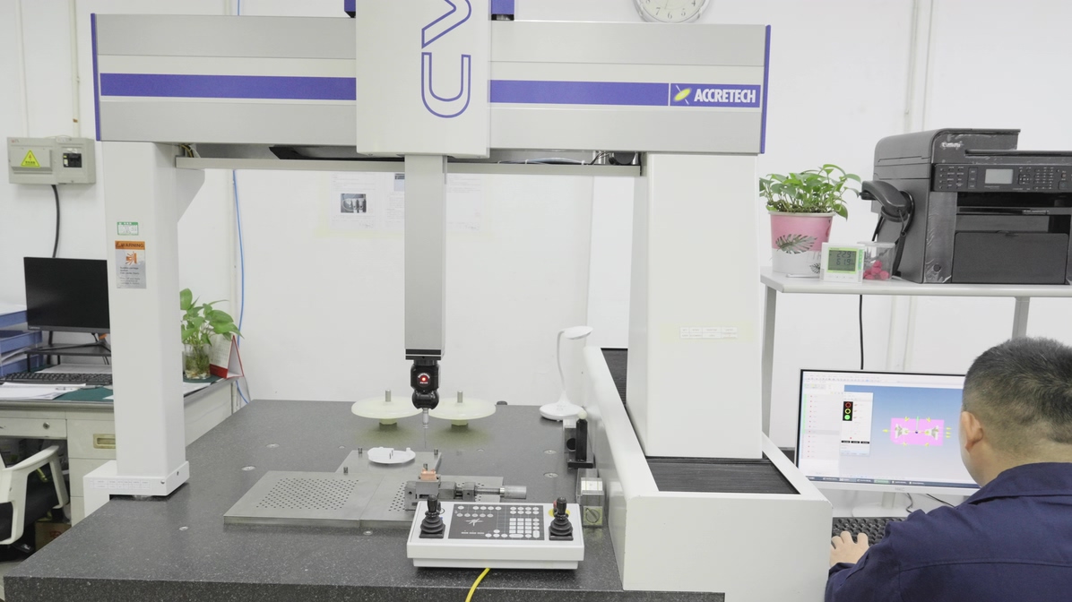
Verified Precision in Mold Manufacturing: 3D CMM Inspection at RiLong
Precision in mold making is not a claim, it is a measurement. A tool that looks correct on the bench can still produce parts outside tolerance if a cavity dimension or a core position is off. 3D CMM inspection closes that gap by measuring the actual geometry against the model before the tool is assembled. Why Measure Before Assembly Once a mold is assembled, access to individual plates and inserts is limited. Measuring components first means a deviation is corrected on a single part rather than discovered as a finished-part defect. The cost difference is large: reworking an insert takes hours, while reworking an assembled tool can take days. Datum Alignment in Practice Each component is aligned to the datums used on its drawing, not to whatever surface is convenient. For a cavity insert, that usually means the mounting face and two edges. Consistent alignment lets measurements from different machines and operators be compared directly. Scanning Versus Touch Probing Touch probing is efficient for known features: hole positions, pocket depths, and plane relationships. Scanning collects dense data across free-form surfaces, which suits curved cavity geometry and allows a full color deviation map. Many shops combine both: probing for critical features, scanning for form. Reading a Deviation Report A deviation map shows where material sits outside tolerance, with a color scale tied to a stated range. The toolmaker uses it to plan a correction: which surface to grind, how much to remove, and whether the correction affects another feature. A report without a scale or a reference model is not actionable. What Gets Checked Cavity and core dimensions against the 3D model Position of holes, dowels, and ejector bores Flatness and parallelism of plates Fit between inserts and pockets Parting line alignment between cavity and core Records That Support the Customer...
read more
29Oct2026
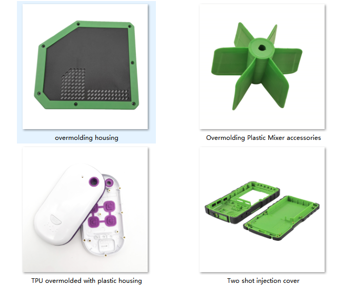
When Plastic Falls Short: Custom Rubber Parts for Demanding Applications
Plastic is the right starting point for many products because it is adaptable, economical, and easy to mold. Some designs, though, only reveal their limits once real conditions apply: a part cracks under load, loses grip, fails to seal, or degrades in a harsh environment. In those cases the answer is often not a different plastic but a custom rubber component engineered for the duty. Where Plastic Reaches Its Limits Rigid thermoplastics are stiff by design. When a part must flex repeatedly, compress to seal, absorb shock, or survive continuous UV and chemical exposure, a plastic grade that meets those needs usually gives up something else such as dimensional stability or cost. Rubber fills that gap with high elongation, elastic recovery, and broad temperature tolerance. Custom Rubber Parts by Function Sealing: O-rings, gaskets, and molded seals that hold pressure and exclude water or dust Grip: buttons, handles, feet, and overmolded surfaces that feel secure in use Damping: mounts and isolators that absorb shock and vibration Protection: boots, covers, and bumpers that deflect impact and abrasion Choosing the Right Elastomer Silicone handles wide temperature range and offers good electrical insulation and biocompatibility options. EPDM resists UV, ozone, and weather, which suits outdoor sealing. Nitrile (NBR) resists oils and fuels and is common in automotive fluid systems. Neoprene balances weather and oil resistance. Fluorosilicone and FKM extend chemical and heat limits at higher cost. Selection should follow the actual fluid, temperature cycle, and compression set requirement rather than a generic preference. Design Rules That Prevent Failure Rubber behaves differently from rigid plastic. Sections should avoid sharp internal corners, and radii should be generous to reduce stress concentration. Compression set depends on squeeze percentage, so groove design must leave room for thermal expansion. Bonded rubber-to-plastic parts need a defined bond line and a...
read more
29Oct2026
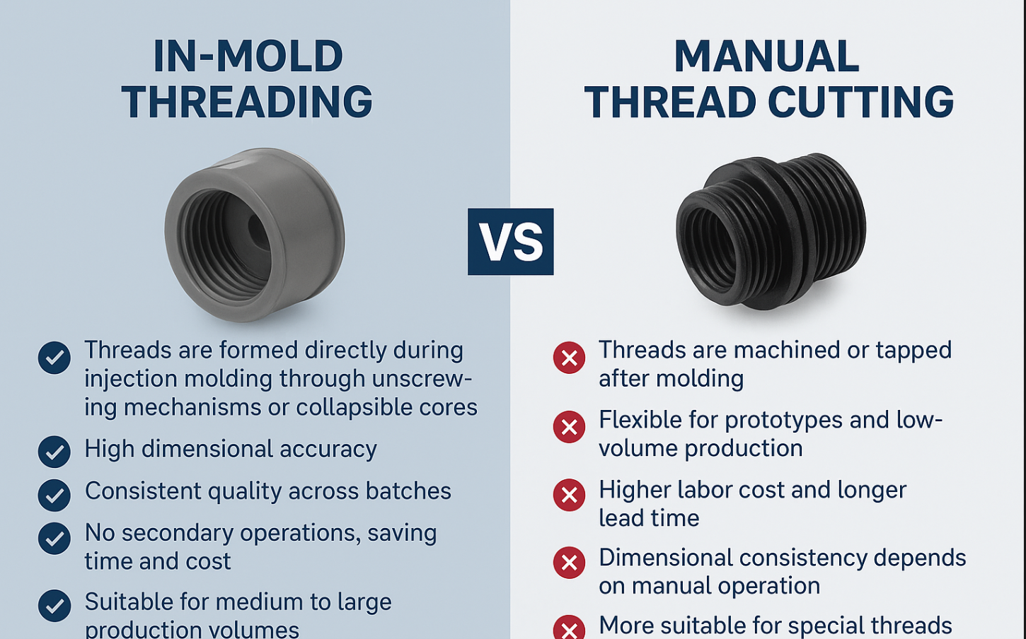
In-Mold Threading vs. Manual Thread Cutting for Plastic Parts
Parts with threaded features force a manufacturing decision that shapes quality, speed, and total expense. The two common routes are in-mold threading and manual thread cutting, and they fit different project profiles. Choosing well depends on volume, tolerance, tooling budget, and how much handling the part can tolerate. How In-Mold Threading Works Threads are formed during molding by an unscrewing mechanism, a collapsible core, or a rotating cavity. The tool forms the thread while the part is produced, so dimensional accuracy is set by steel rather than by an operator. Because the thread is complete when the mold opens, no secondary operation is needed, which removes handling time and the scrap that manual tapping often creates. How Manual Thread Cutting Works Threads are machined or tapped after molding as a separate step. The method is flexible for prototypes, low volumes, and unusual thread specifications. The trade-offs are labor input, longer lead time, and consistency that depends on operator execution and tap wear. Thread flutes, chip clearance, and cross-threading all need attention. Cost Comparison Over Volume In-mold threading needs a more complex tool with gears, racks, or hydraulic drives, which raises the tooling price and the mold maintenance burden. Manual cutting needs a simpler tool but adds a per-part operation cost. The break-even point typically sits at medium volume: below it, the simpler tool plus secondary operation is cheaper; above it, the elimination of a handling step usually wins. Tolerance and Strength Considerations Molded threads usually follow coarse or custom profiles suited to plastic, and their strength depends on material, engagement length, and wall thickness around the thread. Metal inserts, either molded in or installed thermally, are preferred where repeated assembly or high torque is expected. Material choice matters as well: glass-filled resins hold threads better but wear the tool faster....
read more
29Oct2026
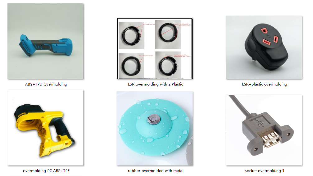
LSR vs Plastic Overmolding: Choosing the Right Material for Your Application
Overmolding lets a product combine structural strength with a soft, sealing, or grippy surface. The hardest question is rarely whether to overmold, but which material should form the second layer. Liquid silicone rubber and engineering plastics both work, and the right answer follows the application rather than a ranking of materials. Where LSR and Plastic Overmolding Diverge The deepest difference is how each material is processed. LSR is a two-part, platinum-cured thermoset that cures inside a heated mold; it cannot be remelted. Thermoplastic overmolding melts a second resin that bonds to the substrate as it cools. That difference drives design freedom, bonding strategy, tolerances, tooling, and the whole production approach. Define What the Overmolded Layer Must Do Before comparing quotes, list the function: sealing against water or dust, soft-touch grip, vibration isolation, electrical insulation, or protection of a display. A layer that must compress and recover favors LSR. A layer that must carry load or provide a hard wearing surface favors a thermoplastic. A practical evaluation covers five connected areas: design, material, process, quality, and production. Design Rules for LSR Overmolding Silicone flows readily and cures at moderate temperature, so it can wrap thin walls and complex contours. Because it bonds chemically to many substrates, mechanical interlocks can be simpler. Shrinkage is low and thermal stability is high, which suits sealing lips and soft buttons. The constraint is that LSR parts are flexible, so they need support in the tool and careful demolding. Design Rules for Thermoplastic Overmolding Thermoplastic overmolding depends on material compatibility. TPE grades bond well to PP, PC/ABS, and PA when the substrate is designed with mechanical interlocks plus chemical affinity. Unequal shrinkage between the two resins causes warpage and sink, so wall sections and gate positions matter. Where an incompatible pair must be used, undercuts and...
read more