

02Nov2026
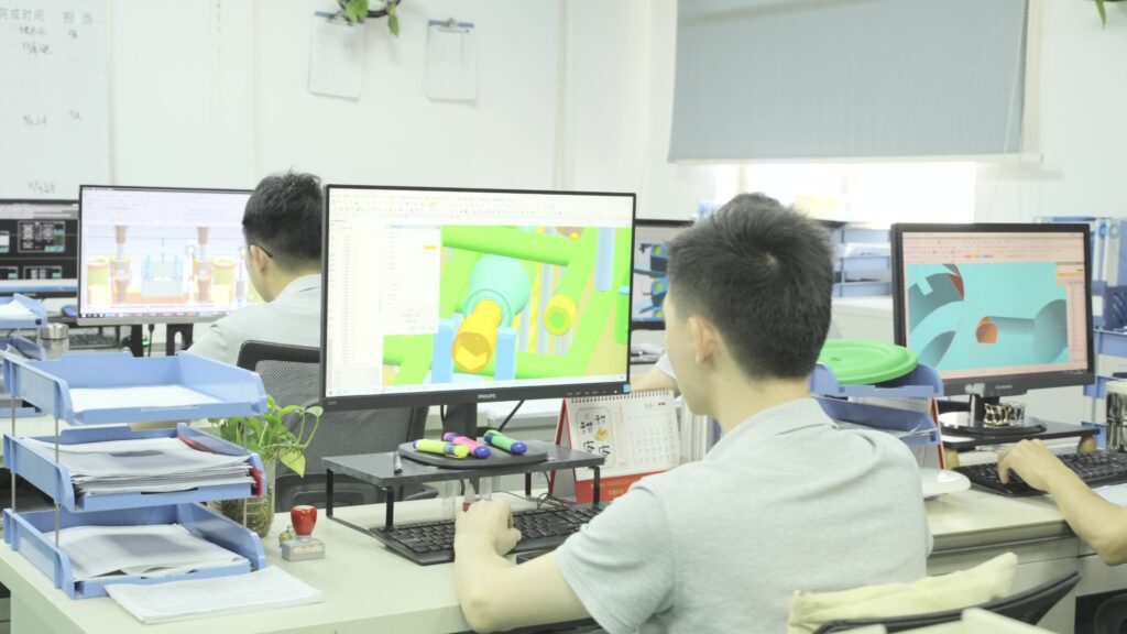
Collaborative LED Top Cover Development: Balancing Light, Branding, and Cost
TCHD explains how collaborative product development helps engineers and sourcing teams balance LED visibility, branding flexibility, cost control, and manufacturability for custom top covers. Drawing on 30+ years of mold design and injection molding experience, TCHD supports projects from concept to production with design, material, process, quality, and production guidance. Clients can share technical, budgetary, or creative challenges for co-creation and technical review.
read more
02Nov2026

Liquid Silicone Rubber in Automotive: Applications, Over-Molding, and Production Considerations
Liquid silicone rubber (LSR) helps automotive teams meet demands for lighter, safer, and more durable vehicles. Its thermal and chemical resistance, elasticity, optical clarity, and soft-touch performance support seals, anti-vibration parts, interior controls, lighting lenses, ADAS sensors, and over-molded hybrid components. This guide reviews design, material, process, quality, and production factors that engineers and sourcing teams should evaluate when specifying LSR.
read more
02Nov2026
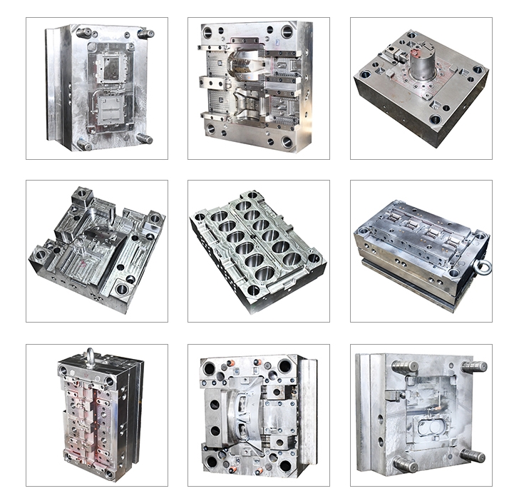
Preventing Injection Mold Failures: Design, Material, Process, and Maintenance Guide
Injection mold failures rarely arrive without warning. Cracks start at a sharp corner, flash appears at one end of a parting line, or a core pin bends a little more each shift. Reading those signals early is cheaper than replacing a cavity block, and most prevention work happens before the tool is ever cut. Injection Mold Failures: Patterns Worth Recognizing Cracking at corners and thin walls, erosion around gates, galling on sliders, stress whitening on ejector pads, and heat checking on hot-runner tips cover most shop-floor failures. Each has a characteristic location and a characteristic cause, which is why the location of a failure is often more informative than its size. Design Causes Sharp internal corners concentrate stress and become crack starters under repeated clamping. Insufficient support plates deflect, so parting surfaces open and flash appears. Uneven cooling pulls the tool into a thermal gradient that fatigues steel. Design reviews and flow simulation before cutting steel catch these issues while changes are still drawings. Material and Steel Selection An unsuitable steel grade fails in predictable ways: soft steel erodes at gates when running glass-filled resin, and unpolished stainless corrodes when running PVC. Substandard mold bases with soft pockets lose insert fit within months. Qualification of the steel supplier and verification of hardness and composition are basic controls that are often skipped. Process Settings That Damage Tools Excessive injection pressure deflects plates and stresses cores. Insufficient pressure produces short shots that operators compensate for by raising temperature, which degrades material and overheats the tool. Clamping force that is too high crushes vents and shut-offs; too low produces flash that is then trimmed with a knife, damaging the parting line. Ejection Problems Undercuts, insufficient draft, or a poorly balanced ejector layout raise ejection force until pins punch through the part or bend....
read more
31Oct2026
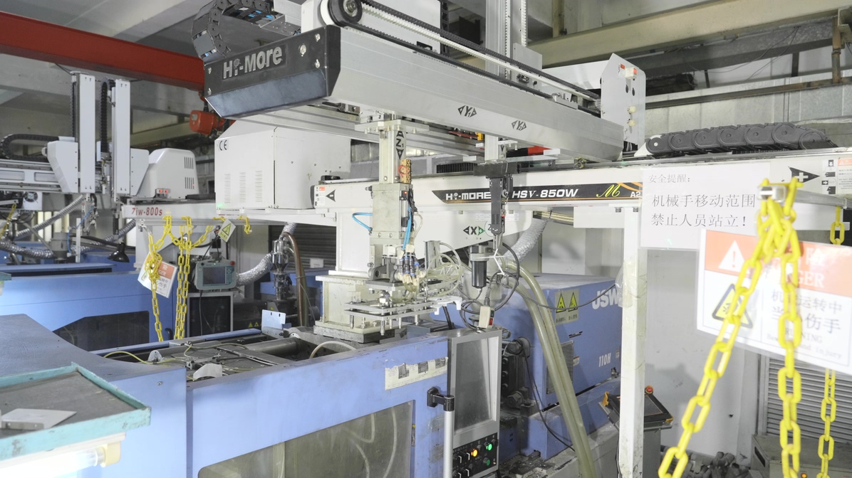
Straight Ejection vs. Insert-Assembled Molds: A Practical Guide to Injection Mold Design
Parts with internal features or undercuts force a tooling decision early: eject the part straight off a core, or mold it in pieces and assemble afterward. The two routes differ in tooling cost, cycle time, part strength, and the amount of secondary labor the program can absorb. How Straight Ejection Works The part is pushed off the core by ejector pins or a stripper plate, with the core shaped so no feature blocks release. Draft, polished surfaces, and balanced ejection prevent drag marks. It is the simplest and fastest route when geometry allows it, because there is no secondary operation and no assembly labor. How Insert-Assembled Molds Work When a feature cannot release, the part is split into two or more moldings that are later joined by ultrasonic welding, snap fit, screws, or adhesive. Each piece has simpler geometry, so the tools are cheaper and easier to maintain. The trade-off is an assembly step, a joint that must be designed, and additional tolerance stack. Tooling Cost Comparison A single tool with a collapsing core or slider costs more than two simple tools in many cases, especially at low volume. But two tools also mean two trials, two maintenance schedules, and two sets of process documentation. At high volume, the elimination of assembly labor usually outweighs the higher tool cost. Part Strength and Joint Design A molded-in feature is continuous material, so it carries load without a joint. An assembled part has an interface that becomes the weak point: a weld line, an adhesive bond, or a snap that can fatigue. Where the feature is structural, straight ejection with a collapsing core is usually the stronger choice. Cycle Time and Labor Straight ejection keeps everything in one cycle, so labor per part is minimal. Assembly adds handling, fixturing, and inspection. In...
read more
31Oct2026
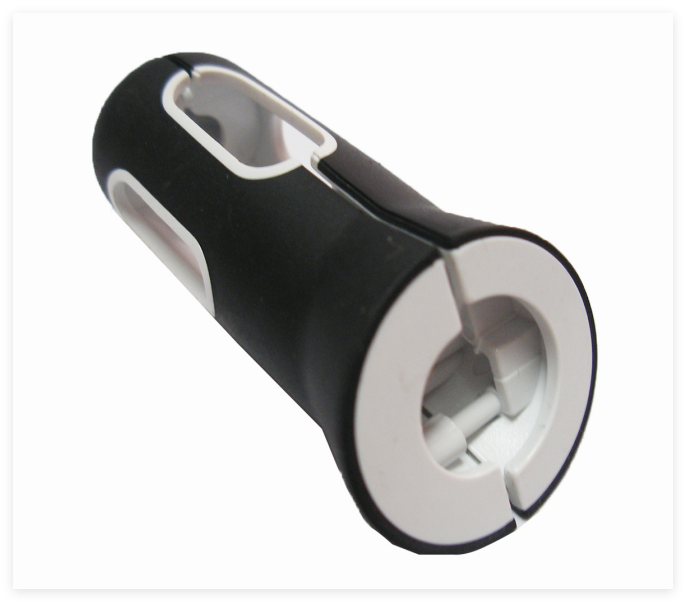
TPE Materials for Sporting Goods: Design, Performance, and Sourcing Guide
TPE for sporting goods solves a problem that rubber and rigid plastic each solve only partly. The material flexes and grips like rubber, processes like a thermoplastic, and can be recycled with the production scrap. For grips, mats, straps, and protective parts, that combination decides both feel and cost. Why TPE for Sporting Goods Fits Grips and Mats Repeated stretching does not permanently deform most TPE grades, so resistance bands keep their tension. High-friction surfaces stay grippy when wet with sweat, which matters for handles and mat surfaces. And unlike thermoset rubber, TPE scrap can be reground and molded again, which supports both cost control and sustainability claims. Grade and Hardness Selection Shore hardness from 30A to 90A covers most sports applications: soft grades for skin contact and cushioning, harder grades for structural grips and wear parts. SEBS-based grades offer good UV and aging resistance for outdoor use; SBS grades are cheaper but degrade faster in sunlight. TPV grades hold up better at high temperature and in dynamic flex. Design Rules for Grips and Mats Keep wall thickness uniform so cooling and shrink stay even Add ribs or texture for grip rather than relying on softness alone Round internal corners to avoid tear initiation Allow for higher shrink than rigid plastic when designing mating features Provide mechanical interlocks where the part is overmolded Flex Zones and Fatigue Where a part bends repeatedly, thickness and radius control fatigue life more than hardness does. A thin section with a generous radius outlasts a thick section with a sharp transition, because stress concentrates at the corner. Overmolding TPE onto Rigid Cores Two-shot molding bonds a TPE skin to a PP, ABS, or PA core without adhesive. Bond strength depends on chemical compatibility and on the core surface temperature at the moment of the...
read more
31Oct2026
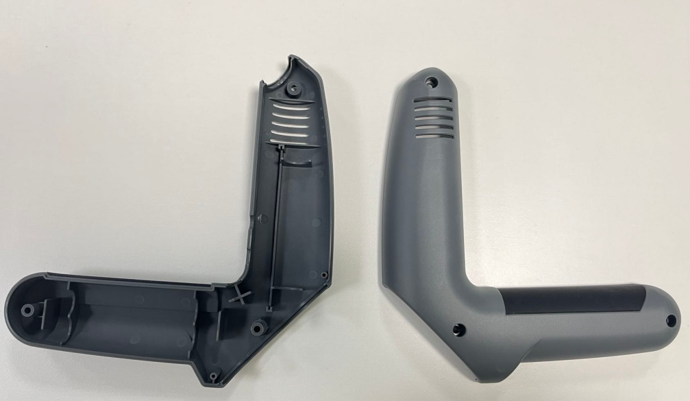
Glass-Filled Nylon Molding: Practical Design and Processing Guide for PA66 + 30% GF
Glass-filled nylon molding looks like ordinary PA66 processing until the fibers reach the gate, the cavity surface, and the ejector pins. A 30 percent glass load raises stiffness and heat resistance, lowers shrinkage, and at the same time accelerates wear, reduces flow, and makes warpage harder to control. The tool and the process have to be designed for the filler, not just the resin. What PA66 With 30% Glass Offers The grade delivers high tensile and flexural strength, good stiffness, short-term heat resistance up to about 250 degrees Celsius, and continuous service near 150. Shrinkage drops and becomes more isotropic than unfilled nylon, which helps hold flatness on structural parts. The same fibers, however, make the melt more viscous and the surface rougher wherever they reach the skin. Steel Selection for an Abrasive, Corrosive Melt Glass fibers erode gate areas and flow paths, and PA66 is mildly acidic, so corrosion and wear arrive together. Hardened grades such as 2316, 2083, 420, and SKD61 treated to HRC 52 or above are common. Nitriding or chrome plating on gates and hot-runner tips extends life where production volumes are high. Gating and Runner Design Sharp corners concentrate fiber impingement and wear quickly. Gate sizes should be generous to reduce shear, since high shear breaks fibers and lowers the strength the filler was chosen to provide. A hot runner needs a smooth, streamlined melt path and tip materials that tolerate abrasion. Glass-Filled Nylon Molding: Process Settings PA66 GF30 needs thorough drying, typically to below 0.2 percent moisture, or the melt hydrolyses and strength falls. Cylinder temperatures run higher than unfilled PA66, with a moderate screw speed to limit fiber breakage. Injection speed should be fast enough to fill before freeze-off but not so fast that shear degrades the melt. Warpage Control Fiber orientation causes...
read more
31Oct2026
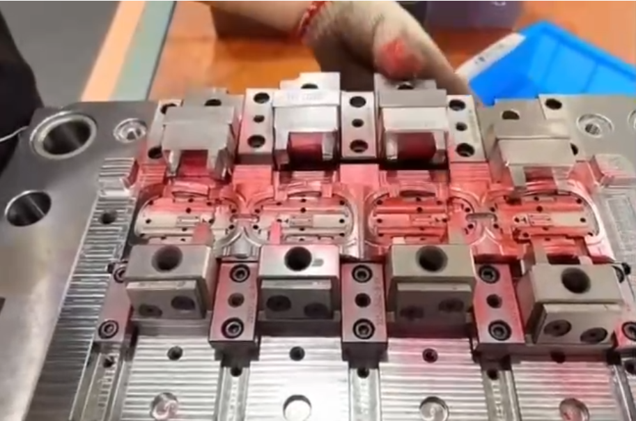
Mold Spotting: The Enduring Role of Red Paste in Precision Mold Alignment
Mold spotting is the practice of coating one mold surface with a thin paste, closing the tool, and reading the transfer pattern that appears. Where the paste smears, the surfaces touched; where it stays intact, a gap remains. It is one of the oldest checks in a toolroom and still one of the fastest ways to find misalignment during assembly. What Mold Spotting Reveals The method exposes contact distribution rather than a single dimension. A shut-off that touches on one corner and gaps on the other will flash in production, yet both corners can measure within tolerance on a CMM. Spotting shows the interaction of two surfaces under real clamping, which is exactly the condition that decides whether a mold seals. Paste, Applicator, and Technique Traditional Prussian blue or red lead paste has largely given way to non-toxic alternatives with similar visibility. The layer must be thin and even: a heavy coat transfers everywhere and hides the pattern, while a starved coat shows nothing. A lint-free swab or a hard roller works better than a brush, and the surface should be clean and dry before application. Reading the Contact Pattern A correct shut-off shows a continuous, even band of transfer along the sealing line. Isolated bright spots mark high points that carry all the load; untouched areas show where the surfaces never met. In a spotting operation for a new tool, the mechanic blue-fits the surfaces by scraping or grinding the high points until the band becomes uniform, repeating the cycle until contact is consistent. Spotting Within the Assembly Sequence Spotting belongs after rough assembly and before the first trial shot, then again after any insert replacement or repair. Checking at each stage keeps errors small: a misaligned dowel found on the bench costs minutes, while the same error discovered...
read more
31Oct2026
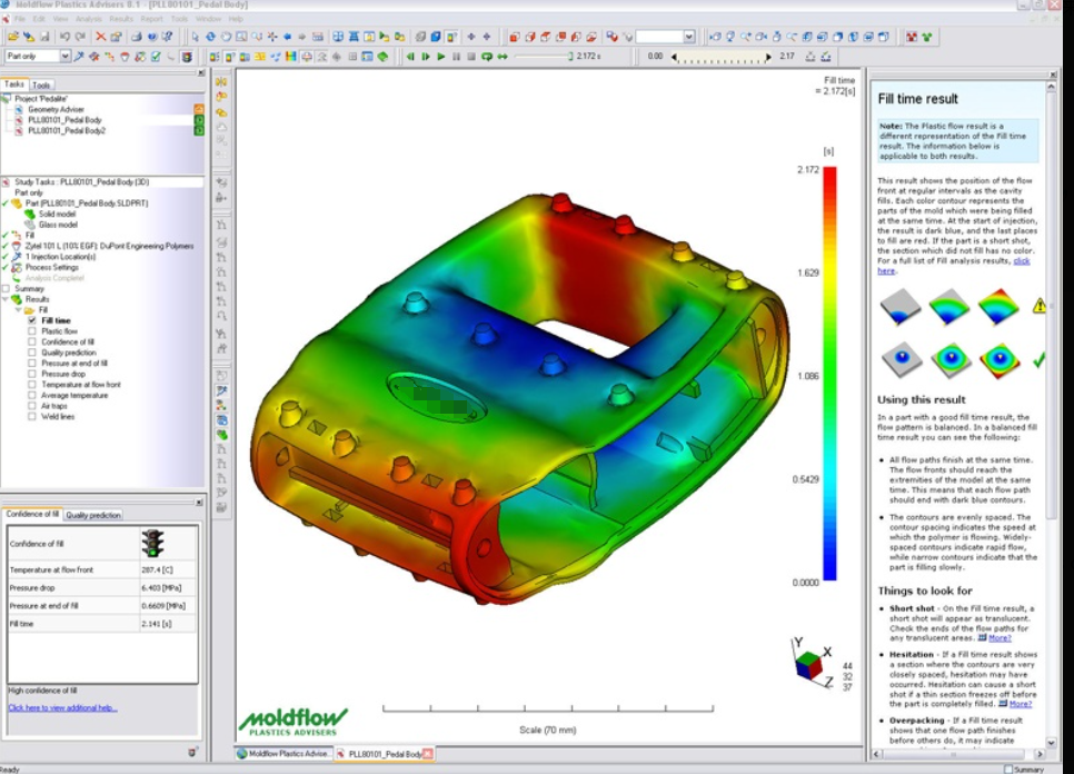
Moldflow Analysis: Real Benefits Before the Mold Is Cut
Moldflow analysis is a simulation of how molten polymer fills, packs, and cools inside a cavity. Run before steel is cut, it turns guesses about gate location and wall thickness into predicted fill patterns, pressures, and temperatures. The value is not the software license; it is the design changes the results prompt. What the Simulation Solves The model includes part geometry, resin grade, gate position, runner layout, cooling channels, and process settings. The solver predicts fill time, pressure at the gate, temperature distribution, shear rate, and volumetric shrinkage. Those outputs describe whether the tool can fill the part within a workable window and where quality risks sit. Defects It Predicts Reliably Short shots from unbalanced filling or thin sections Air traps and weld line locations Sink marks from thick ribs and bosses Warpage driven by uneven cooling or orientation Excessive shear, which degrades heat-sensitive resins When to Run It The most valuable point is during DFM review, while wall thickness and gate position are still open. Running it after the design is frozen confirms decisions rather than improving them. A second run during tool design checks the runner and cooling layout, and a third can support process setup on a new press. Input Quality Decides Output Quality A simulation is only as good as its material data and mesh. Using a generic grade instead of the supplier's characterized data shifts viscosity and shrinkage predictions. A coarse mesh on thin ribs can miss hesitation effects entirely. Reading Results Without Overreacting Every simulation shows some red. The engineering question is whether a predicted deviation matters for the part's function and tolerance. A weld line in a hidden area is acceptable; the same weld line on a sealing surface is not. Results should be reviewed against the drawing, not against a color scale...
read more
31Oct2026
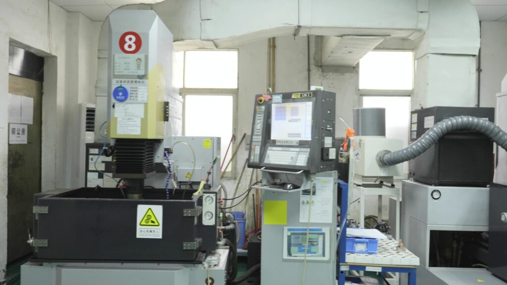
Manufacturing Cost Reduction: Why TCHD Chooses Precision Over Austerity
Manufacturing cost reduction usually begins with a spreadsheet: reduce headcount, delay equipment, renegotiate material. Those moves lower cost this quarter and often raise it over the life of the program. The alternative is slower and less visible, built from design efficiency, tooling quality, and process stability, and it compounds instead of eroding capability. Manufacturing Cost Reduction: Where the Cost Comes From Part cost is material, cycle time, scrap, and inspection, weighted by volume. A design change that removes a thick section can cut cycle time by seconds and eliminate sink, paying back more than a discount on resin. Cost reduction that ignores cycle and scrap is guesswork with a number attached. Design Decisions With the Largest Leverage Uniform wall thickness to shorten cooling and reduce warp Fewer parts and integrated features to remove assembly steps Tolerances specified only where function requires them Gate and ejector locations planned to avoid secondary operations Material chosen for the process window, not just the data sheet Tooling Quality as a Cost Control A tool that runs a two-second-shorter cycle, or that produces one percent less scrap, outperforms a cheaper tool within months. Hardened shut-offs, balanced cooling, and a proper hot runner cost more upfront and reduce the cost per part for the rest of the program. Cheap tooling converts a capital saving into an operating expense. Process Stability and Scrap Scrap is the most expensive form of waste because it consumes material, machine time, and labor before being thrown away. Stable process windows, documented settings, and in-line monitoring reduce variation, and variation is what generates scrap. A plant that measures scrap by cavity finds problems a plant that measures it by month never sees. Automation Where It Pays Robotic take-out, automated assembly, and in-line inspection pay back when volume is high and the process...
read more
31Oct2026
Silicone Rubber Keypad Manufacturing: Materials, Process, and Quality Insights
A silicone rubber keypad looks like a simple part until it fails in the field. Tactile feel, actuation force, legend wear, and dust resistance all depend on decisions made in compounding, tooling, and finishing. Understanding the process makes it easier to write a specification that a supplier can actually meet. Compound Preparation Raw silicone comes as a gum that must be mixed with catalyst, pigment, and fillers. Color matching at this stage matters more than it appears: pigment loading changes cure speed and hardness, so a dark keypad can behave differently from a light one. Batch weight is calculated from cavity volume and specific gravity, and an inaccurate weight shows up as short shots or heavy flash. Silicone Rubber Keypad Molding Methods Compression molding places a preformed blank in an open cavity and closes the press; it is economical for large keys and short runs. Transfer molding pushes compound from a pot through runners, giving better dimensional control for small keys. Liquid silicone rubber injection molding meters two components and cures in a heated tool, which suits high volume and tight tolerances but needs a cold runner system. Tooling and Tactile Design Key feel is a geometry problem. A web thickness that is too thin collapses under finger pressure; too thick and the key will not actuate a dome reliably. Carbon pills or conductive traces create the contact, and their position relative to the dome determines actuation consistency. The tool should be cut with the web and dome in one piece, since a bonded web separates in use. Shore Hardness and Actuation Force Hardness typically runs from 40 to 70 Shore A. Softer compounds feel comfortable but transmit less force to the dome; harder compounds give a crisper click and better durability. Actuation force should be specified as a range...
read more